


Copyright 2013: Maxford USA
Page
Blériot XI: S130926
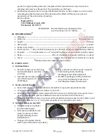
V. SPECIAL FEATURES:
Unique product – The only ARF
available on the market made
of balsa, plywood and
composite materials.
All-moving rudder and
all-moving twin elevators.
Shock-absorbing landing gear.
Shock-absorbing and steerable
tail wheel.
Customer’s option of scale pilot seat,
pilot and dummy engine.
Optional scale-looking spoked wheels.
VI. ASSEMBLY INSTRUCTIONS:
A. TAIL SECTION:
1.
Use your radio or a servo tester to center the elevator and
rudder servos. (You may be interested to learn about servo
testers at
http://www.maxfordusa.com/servo.aspx
.)
2.
Attach EZ-Link connectors to the output arms of the rudder
and elevator servos and use the hardware provided with your
servos to install them in the fuselage.
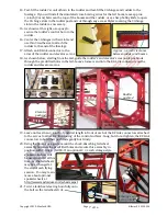
3.
Mark the center of the approx. 16
1/4
-inch long by
4mm-diameter composite elevator torque rod. Then,
while inserting the torque rod through its opening in
the horizontal tailplane, position the three wooden
elevator control-horn parts in the center of the torque
rod. (NOTE: Do
NOT
glue the wooden control-horn
parts together or to the torque rod at this time.)
4.
Center the torque rod within the horizontal tailplane. Mark where the torque rod exits each end
of the horizontal tailplane. Help prevent the torque rod from being accidently glued to the
horizontal tailplane by applying petroleum jelly liberally to the torque rod on each side of the
opening for the elevator’s control horn and where the torque rod exits at both ends of the
horizontal tailplane.
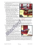
5.
Test-fit the left- and right-side
elevator panels onto the exposed
ends of the elevator torque rod.
Remove the elevators from the
torque rod.
6.
Being careful to not allow any glue
to enter the horizontal tailplane,
apply CA adhesive or epoxy along
the outer length of the right-side
elevator’s torque rod.
Immediately insert this torque rod
into the right-side elevator. Check to
be sure the torque rod remains
centered in the horizontal tailplane
and is able to rotate freely within
the horizontal tailplane.
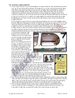
Optional motor, propeller, and
3-cylinder Anzani fan engine
Right end of
the horizontal
tailplane.
Elevator
Rudder
Right-
side
e
e
l
levator
Right-side elevator’s torque rod
Right end of
the horizontal
tailplane.
Adjustable
for motor’s
depth
5
of 16


