Maxford USA Bleriot XI Скачать руководство пользователя страница 13

Copyright 2013:  Maxford USA


Page


Blériot XI:  S130926


e.


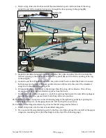
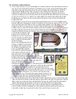
Slide a crimp tube onto the free end of the simulated wing wire at the bottom of the wing. 

Guide the end of the simulated wing wire through the free opening in the spring (

D

).  


f.


Guide the simulated wing wire back through the crimp tube and direct the free end into the 
furthest opening in the bottom-front of the wing panel (

E

) until it exits the opening at the top 

of the wing (

F

). 

g.


Guide the end from 

F

 back through the crimp tube at 

A

. Check or adjust the tension to ensure 

both springs are doubled. With even, gentle tension confirmed, tie the end of the simulated 

wing wire to the end of the spring at 

A

h.


Permanently secure both knots to the spring at 

with a drop of CA adhesive. Trim off any 

excess loose ends of the simulated wing wires from the knots. 

i.


Position the crimp tubes at approx. 

1/4

-inch (5 mm) from the knots at the end of the springs at 

A

 and 

D

. Use pliers to squeeze firmly both crimp tubes into position. 

39.


Install the simulated wing wires near the leading edge of the right wing panel by repeating the 
instructions in step 38 – exchanging the words ‘left’ and ‘right’ as necessary. 

40.


Install the remaining simulated wing wires for the left wing panel as follows: 
a.


Slide a crimp tube onto the end of a simulated wing wire.  

b.


Tie one end of the simulated wing wire to the free end of the spring at the rear left of the upper 
wing-wire-mounting brace (

G

 in the diagram at the top of the following page). 


A


Crimp 

tube


Crimp tube


Spring


C


Detail of 

A


A


13 

of 16


Содержание Bleriot XI

Страница 1: ...cessor it was a tractor configuration monoplane with a partially covered box girder fuselage built from ash with wire cross bracing Harriet Quimby pictured at above right was America s first licensed...

Страница 2: ...tly could cause injury to you or spectators and damage to property Maxford USA provides you with a high quality thoroughly tested model airplane kit with assembly instructions However the quality and...

Страница 3: ...odel airplane check whether the battery is damaged Do NOT attempt to use or recharge a damaged battery II LIMITED WARRANTY LIABILITY WAIVER RETURN POLICY Maxford USA guarantees this kit to be free fro...

Страница 4: ...nd weights are approximate IV PARTS LIST 1 Included items Prebuilt and precovered fuselage horizontal tailplane elevators rudder and wing Included aileron option complete with all associated hinges se...

Страница 5: ...glue the wooden control horn parts together or to the torque rod at this time 4 Center the torque rod within the horizontal tailplane Mark where the torque rod exits each end of the horizontal tailpl...

Страница 6: ...assembly on a flat surface with their flat lower surfaces facing down and aligned to each other Allow the CA adhesive or epoxy to set or cure fully 10 With the horizontal tailplane torque rod and elev...

Страница 7: ...nectors on the rudder and elevator servos 19 Leave not less than 1 2 inch of pushrod length in front of each of the EZ Link connectors attached to the servos to allow for fine tuning of the control su...

Страница 8: ...toward the tail covering both the composite and metal pushrods e Confirm masking tape is still holding the rudder in a straight ahead position Being careful to shrink evenly but not burn the heat shr...

Страница 9: ...irm masking tape is still holding the elevators in a level position aligned with the horizon tal tailplane Being careful to shrink evenly but not burn the heat shrink tubing apply heat from an electri...

Страница 10: ...n the aileron control horns 12 Use CA adhesive to secure the aileron control horns into the holes in the firm balsa wood in each aileron 13 Securely tighten the EZ Link connectors onto the aileron pus...

Страница 11: ...be moved forward See section VII 1 on page 15 25 Temporarily attach your motor to the front former of the fuselage as noted above do NOT permanently mount your motor to the front former at this time 2...

Страница 12: ...sary slightly rebend the wire legs of the lower wing wire mounting brace to position each of its metal mounting tabs over a guide hole in the bottom of the fuselage 37 Secure the lower wing wire brace...

Страница 13: ...ently secure both knots to the spring at A with a drop of CA adhesive Trim off any excess loose ends of the simulated wing wires from the knots i Position the crimp tubes at approx 1 4 inch 5 mm from...

Страница 14: ...per wing wire mounting brace at G i Permanently secure both knots to the spring with a drop of CA adhesive Trim off any excess loose ends of the simulated wing wire from the knots j Position the crimp...

Страница 15: ...ar from the fuselage and drill 1 8 inch holes at the eight scribed locations Using the hardware supplied with your motor permanently attach the motor with its output shaft aligned at the center of the...

Страница 16: ...of the landing gear 2 Check the Mylar covering material s joints and surfaces If necessary carefully use an iron on medium heat to secure the edges and to tighten any loosened areas Recheck and retig...

Страница 17: ...axford USA Order by telephone as shown on page 16 in the Instruction Manual 3 If you will install an optional simulated Anzani 3 cylinder fan semiradial engine after permanently attaching the motor to...

Страница 18: ...sert the wire into the fuselage through the opening in the lower left corner of former 4 b Guide the wire through the fuselage out through the opening in the lower right corner of former 4 and back th...

Страница 19: ...tops of formers 8 7 6 and 5 i As shown below insert the wire into the fuselage through the opening in the upper right corner of former 4 Guide the wire through the fuselage and out through the openin...

Страница 20: ...gh the holes in in the lower left corner of former 4 pull the wire snug and form a knot s At the back of former 4 apply CA adhesive to both knots Trim off the loose ends of excess wire t Insert the en...

Отзывы: