


Copyright 2013: Maxford USA
Page
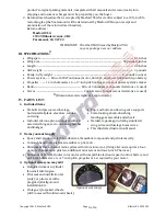
Blériot XI: S130926
31.
Make all necessary connections to your radio’s receiver: ESC’s servo-type connector to
THROTTLE
;
rudder’s connector to
RUDDER
; elevator’s connector to
ELEVATOR
, and if you are using ailerons
connect the aileron’s Y harness to
AILERON
.
32.
Secure your battery to the tray with hook-and-loop material. Follow the instructions given by
your radio receiver’s manufacturer to secure your receiver within the cockpit.
33.
Set your transmitter’s throttle and throttle trim controls to minimum and switch ON your
transmitter. Connect your LiPo flight battery to the ESC. After you hear a series of initialization
sounds, carefully and slowly raise the transmitter’s throttle to no more than 25% of maximum
and observe the propeller’s direction of rotation – the propeller should be rotating clockwise as
viewed from the rear of the airplane.
34.
Return the transmitter’s throttle control to minimum and disconnect the ESC from the battery.
35.
If the motor rotated in the clockwise (correct) direction as viewed from the rear of the airplane,
disconnect the battery, switch OFF and set your transmitter aside. If the motor powered up in the
wrong direction, swap either two of the three ESC-to-motor wires and repeat the test to ensure
the motor rotates in the correct direction.
36.
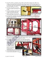
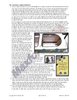
If necessary, slightly rebend the wire ‘legs’ of the lower wing-wire-mounting brace to position
each of its metal mounting tabs over a guide hole in the bottom of the fuselage.
37.
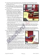
Secure the lower wing-wire brace to the bottom of the fuselage by driving four approx.
5/16
-inch
(1 cm) long screws into the guide holes in the bottom of the fusealge.
38.
Install the simulated ‘wires’ near the leading edge of the
left wing panel as follows: (NOTE: The simulated ‘wires’
hold the wing panels against the fuselage and enable the
wing to be removed for transport. However, if an easily
removable wing is not a desired feature, the wings may
be glued onto the wing rods with 5-minute epoxy; the
simulated wing wires are then only ‘cosmetic’ and may
be omitted by the owner/builder if desired.)
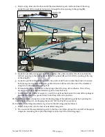
a.
Slide a crimp tube onto a ‘wire.’
b.
As shown on the following page, tie one end of the
‘wire’ to the free end of the spring at the front left of
the upper wing-wire-mounting brace (
A
in the
photograph on the following page).
c.
Guide the free end of the ‘wire’ from
A
down
into the nearest opening in the top of the wing
panel (
B
) until it exits at the bottom of the wing
(
C
). Pull the ‘wire’ from
C
until the ‘wire’
between
A
and
B
is snug and the spring at
A
is
approx. doubled.
d.
Attach a spring to the same anchor point used
for the already connected lower end of the
landing-gear’s spring.
Lower wing-
wire brace attached
to the bottom of the
fuselage with four
approx.
5/16
-inch
long (1 cm) screws.
Attach one end of a spring to anchor
point at bottom of landing gear.
12
of 16


