background image


NORTH, CENTRAL 

AND SOUTH AMERICA 

Tel +1.405.755.1600 

Fax +1.405.755.8425 

[email protected] 

www.maxcessintl.com 

EUROPE, MIDDLE EAST 

AND AFRICA 

Tel +49.6195.7002.0 

Fax +49.6195.7002.933 

[email protected] 

www.maxcess.eu


CHINA 


Tel +86.756.881.9398 

Fax +86.756.881.9393 

[email protected] 

www.maxcessintl.com.cn


INDIA 


Tel +91.22.27602633 

Fax +91.22.27602634 

[email protected] 

www.maxcess.in


JAPAN 


Tel +81.43.421.1622 

Fax +81.43.421.2895 

[email protected] 

www.maxcess.jp


KOREA, TAIWAN, 

AND SE ASIA 

Tel +65.9620.3883 

Fax +65.6235.4818 

[email protected] 


© 2013 Maxcess 

Содержание FIFE-500-XL

Страница 1: ...FIFE 500 XL User Manual EN Medium Web Guiding System MI 2 267 1 D ...

Страница 2: ......

Страница 3: ...Menu Tree 3 7 Servo Center Menu Tree 3 9 Automatic Menu Tree 3 10 Security Strategy 3 11 Authorization Levels 3 11 Access Modes 3 12 Keypad Operation 3 13 MENU DESCRIPTIONS 4 1 Security 4 1 Logout 4 1 Login 4 1 Passwords 4 2 Menu Protection 4 3 Display 4 3 Language 4 4 Brightness 4 4 Rotate 4 6 Calibrate Touch 4 7 OI Settings 4 8 Service 4 10 About 4 10 Measure 4 11 Control Outputs 4 13 Color Test...

Страница 4: ...tions 4 32 Power On Mode 4 34 Backup 4 35 Restore 4 36 Hardlock 4 37 Name 4 38 Network 4 39 Line Speed 4 40 MCP 05 Option 4 43 MCP 05 Operation 4 46 DIGITAL INPUT OUTPUT MATRIX 5 1 Digital Input Matrix 5 1 Digital Output Matrix 5 2 SYSTEM NOTES 6 1 TROUBLESHOOTING 7 1 Fault Diagnostics and Rectification 7 1 SERVICE AND REPLACEMENT PARTS 8 1 ...

Страница 5: ...cepts with each directed at a particular part of the task The basic concepts are Sense the lateral position of the web edge sensors Generate a correction signal proportional to the error signal processor Apply forces to the web to non destructively move it to the desired location motor controlled mechanical pivoting rollers Sensing Sensing the lateral position of the web edge can be done by a vari...

Страница 6: ...atic guide centering and remote control support Web guiding The output of the signal processor is fed to a motor that is coupled to a set of pivoting rollers In order to ensure enough friction exists between the moving web and the guide rollers the web path and location of the guide rollers are designed to ensure a certain amount of surface area contact with the roller surface Under these conditio...

Страница 7: ...owing The content of these operating instructions Any safety instructions on the device The machine manufacturer s specifications All national state and local requirements for installation accident prevention and environmental protection Information about safety instructions The safety instructions and symbols described in this section are used in these operating instructions They are used to avoi...

Страница 8: ...at may result in bodily injuries or damage to device or material WARNING CAUTION Danger due to crushing Reference to danger of injury caused by crushing WARNING CAUTION Danger due to cutting Reference to danger of injury caused by cutting WARNING CAUTION Danger due to voltage electric shock Reference to danger of injury caused by electric shock due to voltage WARNING CAUTION Danger due to hot surf...

Страница 9: ...operation Only perform installation maintenance or repair tasks on the web guiding system when the machine has been stopped and is secured from being turned on Only perform installation maintenance or repair tasks on the web guiding system when there is no electrical power in the system The web guiding system must be securely mounted before being placed in operation Only replacement parts obtained...

Страница 10: ...ing or rotating parts Appropriate protective guards must be installed by the user according to his use of this product Maintenance and Repair WARNING Death or injury can result from unexpected movement Protect against unexpected movement by removing electrical power from the web guiding system and the machine into which the web guiding system is installed WARNING Danger of injury from crushing Mai...

Страница 11: ...commended that standard safeguards be taken to prevent injury During servicing of the equipment to prevent injury to personnel it is recommended that standard Lockout Tagout procedures be used The FIFE 500 XL Operator Interface should not be used while the machine is running If it is necessary for the operator to use the Operator Interface while the machine is running precautions must be taken to ...

Страница 12: ...ng button in a green color Other buttons are blue The horizontal section at the top above the line contains the status bar which always contains the screen number It may also indicate statuses errors and digital I O The middle section indicates the current Operation Mode the selected sensor signal level in a bar graph and the position of the system guide point This section also contains buttons fo...

Страница 13: ...r and Manual and indicates the current Operation Mode selection by displaying that button in a green color The section just below the Operation Mode buttons indicates the current Operation Mode the selected sensor signal level in a bar graph and the position of the system guide point This section also contains the Guidepoint Shift buttons and the Guidepoint Reset button The section below that just...

Страница 14: ...o arrow buttons to adjust the System Guide Point while in Automatic Mode or Manual Mode Use the center button to reset the System Guide Point to the default value which is 50 of the sensor bandwidth The slider control indicates the guide point position The color of the guide point pointer is blue when the guide point is zero yellow when a guide point shift is present and red when the guide point s...

Страница 15: ...r Interface are directed to all drives in the network simultaneously BACK Use this menu navigation button to return to the previous menu level HOME Use to return to the Operator Level screen MENU ARROWS Use in the menu system to page forward or backward when multiple pages of menu choices are available The arrows are disabled when no more choices are available in the respective direction ACCEPT Us...

Страница 16: ... screen since the SENSOR button already contains this information MENU TIMEOUT The menu screens in the FIFE 500 XL Web Guiding System close automatically after 3 minutes of touch screen inactivity The inactivity timeout option and the timeout value are configurable The clock icons will appear during stages of the timeout process as the inactivity timer counts down If a timeout occurs the respectiv...

Страница 17: ...AGE ERROR This error icon appears when the input voltage motor rail voltage or internal 12 volt power is outside acceptable range NETWORK ERROR This icon appears when the operator interface is unable to gain network control LINKED MODE This icon appears when the linked mode is active Linked mode is used in networked systems to send the Automatic Manual and Servo Center commands to all network devi...

Страница 18: ...nu is described in more detail later in this document 1X MANUAL SETUP 1X 1 1 SECURITY 1X 1 1 1 LOGOUT 1X 1 1 2 LOGIN 1X 1 1 3 PASSWORDS 1X 1 1 4 MENU PROTECTION 1X 1 2 DISPLAY 1X 1 2 1 LANGUAGE 1X 1 2 2 BRIGHTNESS 1X 1 2 3 ROTATE 1X 1 2 4 CALIBRATE TOUCH 1X 1 2 5 OI SETTINGS 1X 1 3 SERVICE 1X 1 3 1 ABOUT 1X 1 3 2 MEASURE 1X 1 3 3 CONTROL OUTPUTS 1X 1 3 4 COLOR TEST 1X 1 3 5 MOTOR TYPE 1X 1 3 6 COM...

Страница 19: ... 1 D 1X 1 6 GAIN 1X 1 7 SENSOR SETUP 1X 1 8 AUTOSETUP Page forward back 1X 2 1 GUIDE SETTINGS 1X 2 2 CONTROL OPTIONS 1X 2 3 POWER ON MODE 1X 2 4 BACKUP 1X 2 5 RESTORE 1X 2 6 HARDLOCK 1X 2 7 NAME 1X 2 8 NETWORK Page forward back 1X 3 1 LINE SPEED 1X 3 2 MCP 05 OPTION ...

Страница 20: ...ENU PROTECTION 2X 1 2 DISPLAY 2X 1 2 1 LANGUAGE 2X 1 2 2 BRIGHTNESS 2X 1 2 3 ROTATE 2X 1 2 4 CALIBRATE TOUCH 2X 1 2 5 OI SETTINGS 2X 1 3 SERVICE 2X 1 3 1 ABOUT 2X 1 3 2 MEASURE 2X 1 3 3 CONTROL OUTPUTS 2X 1 3 4 COLOR TEST 2X 1 3 5 MOTOR TYPE 2X 1 3 6 COM STATISTICS 2X 1 4 REMOTE CONTROL 2X 1 5 ASC 2X 1 5 1 ASC OFF 2X 1 5 2 ASC ON 2X 1 5 3 ASC SETTINGS 2X 1 6 SC GAIN 2X 1 7 CONTROL OPTIONS ...

Страница 21: ...NU PROTECTION 3X 1 2 DISPLAY 3X 1 2 1 LANGUAGE 3X 1 2 2 BRIGHTNESS 3X 1 2 3 ROTATE 3X 1 2 4 CALIBRATE TOUCH 3X 1 2 5 OI SETTINGS 3X 1 3 SERVICE 3X 1 3 1 ABOUT 3X 1 3 2 MEASURE 3X 1 3 3 CONTROL OUTPUTS 3X 1 3 4 COLOR TEST 3X 1 3 5 MOTOR TYPE 3X 1 3 6 COM STATISTICS 3X 1 4 REMOTE CONTROL 3X 1 5 ASC 3X 1 5 1 ASC OFF 3X 1 5 2 ASC ON 3X 1 5 3 ASC SETTINGS 3X 1 6 GAIN 3X 1 7 CONTROL OPTIONS ...

Страница 22: ...h three access modes for each level When security is enabled the current login authorization level is indicated by a key icon in the status bar with the authorization level next to it Level 1 has the lowest privileges and level 3 has the highest If security is not in use these icons will not appear The three authorization levels and their associated icons are described below OPERATOR LEVEL 1 This ...

Страница 23: ...ACCESS The lock icon superimposed on a button indicates that access is not allowed from the current login authorization level Pressing the button will prompt for numeric pass code entry and will only allow access if the entered code raises the login authorization level high enough to permit access READ ONLY ACCESS The magnifier icon superimposed on a button indicates that the menu has read only ac...

Страница 24: ...ry format similar to data entry using a calculator where new values appear on the right and shift existing data left The exception to this is when the first button is pressed the displayed value is cleared first Some entries accept a decimal point and polarity When editing values that do not accept decimal points or signed entry these buttons will be disabled The CLEAR button erases the current en...

Страница 25: ...f the applicable limits the entered number and the violated limit are marked in red as shown in the example below If this occurs the CLEAR button may be used to erase the entry and try again or the CANCEL button will cancel the editing operation and close the window Other controls Unit Optionally shows the active unit of measurement for the edited value Maximum Shows the maximum allowed value Mini...

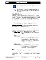
Страница 26: ...to one if security is enabled Navigation MANUAL SERVO CENTER AUTOMATIC SETUP SECURITY LOGOUT This button is ignored if security is not enabled LOGIN If security has been enabled login prompts for numeric code entry The authorization level is changed according to the entered code Navigation MANUAL SERVO CENTER AUTOMATIC SETUP SECURITY LOGIN Enter the password and press the ENTER key Press the CANCE...

Страница 27: ...ol to modify the timeout value Access level 2 The level 2 pass code Touch the edit control to enter or modify the level 2 pass code and enter the new pass code when prompted The same code must be entered twice for verification Access level 3 The level 3 administrator pass code Touch the edit control to enter or modify the level 2 pass code and enter the new pass code when prompted The same code mu...

Страница 28: ... the list Setup can be used to block access to all setup menus To modify an entry select the menu entry in the list and press the button in the columns labeled as level 1 2 or 3 as needed to cycle through the permission options of Full Read only or No access The CLEAR button applies full access to all entries The DEFAULT button presets the factory default settings Press ACCEPT to apply changes and...

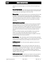
Страница 29: ... MANUAL SERVO CENTER AUTOMATIC SETUP DISPLAY LANGUAGE Use the page arrows to move forward or backward to see more choices Select the desired language and press ACCEPT to save The screen will return to the Operator Level screen Press CANCEL to exit without saving changes and return to the previous screen BRIGHTNESS Adjusts the LCD backlight intensity Navigation MANUAL SERVO CENTER AUTOMATIC SETUP ...

Страница 30: ...the arrow buttons for fine control of the screen brightness or use the slider handle for quick movement Press this button to set the brightness level to 50 Press ACCEPT to save new brightness setting and return to the previous screen Press CANCEL to return to the previous screen without saving changes ...

Страница 31: ...the operator interface Choose from 0 90 180 270 settings Navigation MANUAL SERVO CENTER AUTOMATIC SETUP DISPLAY ROTATE Select the desired screen rotation and press the ACCEPT button to save The screen will go blank for a moment and restart in the new orientation Press CANCEL to return to the previous screen without saving changes ...

Страница 32: ...y This is only necessary if button reactions appear to be out of sync with the displayed button locations The screen will go blank for a moment followed by prompts to touch the screen in two locations Note A stylus is recommended to improve the accuracy of calibration Navigation MANUAL SERVO CENTER AUTOMATIC SETUP DISPLAY CALIBRATE TOUCH ...

Страница 33: ...mended in a non networked system OI Termination Should always be checked in a non networked system In a networked system should be checked if the OI is at the end of the line and unchecked otherwise Refer to the supplementary user instructions Fife FIFE 500 XL Networking of Web Guiding Systems MI 1 919 for details Bargraph update speed This slider controls the update speed of the sensor signal bar...

Страница 34: ...vo Center modes sets the guide point of the active sensor mode to match the current location of the web This allows guiding to begin at the current web location when the Automatic mode is initiated Enable link option For use in networked systems Checking this option enables an additional button in the drive select area of the Operator Level screen When the link option is enabled and the link mode ...

Страница 35: ...L MI 2 267 1 D SERVICE The service submenu provides access to maintenance screens The service submenu is available in all operation modes ABOUT This screen provides firmware version information Navigation MANUAL SERVO CENTER AUTOMATIC SETUP SERVICE ABOUT ...

Страница 36: ...monitoring motor current Press the respective tab to bring it forward for viewing This menu is immune from any configured menu timeouts Navigation MANUAL SERVO CENTER AUTOMATIC SETUP SERVICE MEASURE Voltages that are out of range will be marked with a red background as shown below Notice that the voltage error icon is visible on the status bar Since voltages are monitored at all times the status b...

Страница 37: ...maxcessintl com FIFE 500 XL MI 2 267 1 D indicating the motor current and polarity A graph is also present to display history of the recent motor current activity Press ACCEPT to close this menu and return to the previous screen ...

Страница 38: ... MANUAL SERVO CENTER AUTOMATIC SETUP SERVICE CONTROL OUTPUTS Press OK to close this window Press ACCEPT to return to the previous screen A reminder message will be displayed indicating the digital outputs will resume their normal operation WARNING Death or injury can result from unexpected movement The web guiding system has four independent outputs that can be connected to other components into w...

Страница 39: ...ings which would most likely identify hardware related signal issues Horz Vert This control selects the gradient direction horizontal or vertical The red green and blue buttons on each side cycle through an 8 bit binary sequence selected to drive each signal separately in the color circuitry Small changes present in this sequences typically produce no visually discernable screen change and are onl...

Страница 40: ...o view the configured motor type Navigation MANUAL SERVO CENTER AUTOMATIC SETUP SERVICE MOTOR TYPE The resulting screen will display the currently configured motor type as shown in the example below The motor type for your system may be different than that shown here Press CANCEL to close this menu ...

Страница 41: ...e total packets received Rcv Mine Indicates the total number of packets received that were addressed to the respective device Rcv Not mine The number of packets received and discarded because they were not addressed to the respective device Buffer full Indicates the number of packets discarded because the devices receive buffers were full Bad checksum Each packet received is verified using a check...

Страница 42: ...ksum fault should not increase rapidly Token Cycles This counter will only increase in systems containing multiple Operator Interfaces It signifies the activity conducted by multiple Operator Interface devices to share access to the communication bus Press the ACCEPT button to return to the previous screen ...

Страница 43: ...NTROL Status bar indicators Digital inputs disabled red down arrow Digital outputs are disabled red up arrow Both input and output signals are disabled red arrows Press ACCEPT to save changes and return to the previous screen Press CANCEL to close this menu without saving changes WARNING Death or injury can result from unexpected movement The web guiding system has four independent outputs that ca...

Страница 44: ...ASC processing if ASC control has been enabled in the configuration screen for the active sensor mode Each sensor mode can be individually configured with different ASC settings The availability of ASC for each sensor mode is among the configurable settings Navigation MANUAL SERVO CENTER AUTOMATIC SETUP ASC ASC ON This icon will be displayed in the status bar when ASC is enabled The ASC icon will ...

Страница 45: ...sholds Typically this is the same sensor used for guiding but in some applications it could be desirable to monitor a different input Source input choices include the sensor signal S1 S2 S1 S2 or S1S2 Mode The mode setting controls how the source signal threshold is processed These modes are used configure ASC operation for specific application requirements There are 6 modes available Above Signal...

Страница 46: ...AND less than the positive threshold ASC Threshold 2 Neg The ASC signal negative threshold Touch the threshold value to open an edit screen to change it ASC Threshold 1 Pos The ASC signal positive threshold Touch the threshold value to open an edit screen to change it Press ACCEPT to save changes and return to the previous screen Press CANCEL to exit without saving changes and return to the previo...

Страница 47: ... soon as it is changed while in this menu so the effects of gain changes can be observed if the system is in Automatic mode The graph area shows the amplified output of the active sensor signal to provide feedback about guide movement as the gain is changed Press ACCEPT to save changes and return to the previous screen Press CANCEL to exit without saving changes and return to the previous screen I...

Страница 48: ...e but the sensor signal is not within the allowable range If the Auto setup button is not available use the larger arrow buttons to jog the guide in either direction until the sensor signal is within the allowable range and the Auto setup button is available Press AUTOSETUP to initiate the auto setup cycle The guide will move a short distance and the system gain value will be automatically set The...

Страница 49: ...reen If the gain has been changed it will be restored to its previous value WARNING Death or injury can result from unexpected movement Auto setup operation causes guide movement Take appropriate precautions to ensure no one is in the vicinity of the guide path of travel ...

Страница 50: ...m gain or for fast gain changes use the slider control The gain value is applied as soon as it is changed while in this menu so the effects of the servo center gain changes can be observed The graph area shows the amplified output of the servo center transducer to provide feedback about guide movement as the gain is changed Press ACCEPT to save changes and return to the previous screen Press CANCE...

Страница 51: ...g System can store recall up to four sets of calibration settings for S1 and S2 supporting the possibility to store and quickly recall sensor settings for four different web opacities Button Descriptions CALIBRATION SET These buttons select one of four sets of calibration values Only one calibration set may be active at any given time with the active set indicated by the green LED on the button fa...

Страница 52: ... of the last calibration and return to the previous screen Any changes to the sensor calibration set is restored to its previous setting Calibration Procedure Select which set of calibration values will be used Select S1 or S2 sensor input Press the START CALIBRATION button The bar graph indicator will be rescaled to show the full signal range of 20mA to 20mA on the selected sensor input The senso...

Страница 53: ...s screen Note If a different calibration set is chosen after a successful calibration has been completed it will be permanently saved before switching to the new calibration set In this case exiting this menu with the CANCEL button will not restore this calibration to its previous setting If the sensor signal difference between the uncovered and covered states is too low the web opacity is beyond ...

Страница 54: ... is performed using the sensor mode that has been selected from the Operator Level screen Before auto setup can begin the web must be within the selected sensor field of view The bar graph indicator shows the acceptable limits for the sensor signal and the AUTOSETUP button will remain disabled until the correct conditions are present Use the jog buttons to position the web edge near the center of ...

Страница 55: ... not restore previous gain and polarity settings WARNING Death or injury can result from unexpected movement Auto setup operation causes guide movement Take appropriate precautions to ensure no one is in the vicinity of the guide path of travel Note For most installations the Auto Setup routine sets the system gain at the proper level for good guiding performance However in some applications for o...

Страница 56: ...n if guide correction moves in the wrong direction Jog polarity controls the direction of guide movement when the jog buttons are pressed Gain The gain controls display the gain settings for each mode of operation The gain values are set automatically if the auto setup procedure is used This screen provides controls to support manual gain tuning To edit a gain setting touch the desired gain value ...

Страница 57: ...e menu will not permit saving a configuration with all checkboxes cleared Jog Enable These three checkboxes enable or disable jog operations in automatic servo center and manual operation modes A checked box indicates jogs are permitted When jogs are disabled the jog buttons on the Operator Level screen are unavailable GP Enable These checkboxes enable or disable the system guide point controls on...

Страница 58: ...e Used to select the desired icon appearance for sensor modes The default setting uses a standard C style sensor appearance but line sensors can be specified when applicable Note When line sensor icons are selected the center guiding mode consisting of S1 S2 is disabled since it has no purpose in line guiding applications Press ACCEPT to save changes made to this screen Press CANCEL to exit withou...

Страница 59: ...lt button selects the factory setting which is Last mode used Power cycles shows the number of power cycles the system has recorded Press ACCEPT to save changes and return to the previous screen Press CANCEL to close this screen and return to the previous screen without saving any changes WARNING Death or injury can result from unexpected movement Selecting Automatic or Servo Center modes for powe...

Страница 60: ...ese settings can be recalled using the RESTORE menu Navigation MANUAL SETUP Page forward BACKUP If a backup already exists the system will ask for confirmation before replacing it The screen below will be shown after the backup completes Press the OK button to continue and return to the previous menu screen Press OK to close this window ...

Страница 61: ...UAL SETUP Page forward RESTORE If no backup image is present or it is corrupted the following message will appear Restore is not possible in this case Press OK to close this window Note Restore reloads all user configurable settings such as gains polarities etc In order to prevent unintended password modification restore does not replace active passwords from the backup image ...

Страница 62: ...ned to prevent movement from outside forces while in manual mode Hard lock if enabled is applied in all cases where manual posture is active such as when external lock from the digital inputs is active Navigation MANUAL SETUP Page forward HARDLOCK Enable Hardlock Check this box to turn the hardlock feature on Hardlock Polarity Sets the hardlock correction polarity Hardlock Gain Sets the hardlock c...

Страница 63: ...worked environment to identify the connected drive Navigation MANUAL SETUP Page forward NAME Enter up to 15 characters to describe the drive Edit functions include Del Delete characters to the right of the cursor Back Backspace function deletes characters to the left of the cursor The cursor can be moved by touching the desired position in the edit control Press ACCEPT to save changes Press CANCEL...

Страница 64: ...the network Select a device to be presented with configuration options for it Device address Used to assign a new address to the device Name This control only appears when configuring a drive Use it to specify the drive name which will appear on the Operator Level screen when connected to this drive Termination If the device supports configurable termination an additional checkbox will be present ...

Страница 65: ... without saving any changes LINE SPEED This menu is used to calibrate the line speed input signal and configure the line speed option Navigation MANUAL SETUP Page forward Page forward LINE SPEED Line speed control is used to automatically increase or decrease guide correction speed according to web travel speed The guide correction speed influence applies only in the Automatic mode The line speed ...

Страница 66: ...ximum line speeds then correlate to minimum and maximum guide correction speed Line speed calibration operates correctly regardless of line speed input polarity For example a Minimum Speed producing 10mA with a corresponding Maximum Speed producing 2mA is acceptable In all cases the Minimum Speed must be presented first Start Calibration Press this button to start the line speed input calibration ...

Страница 67: ...xcessintl com FIFE 500 XL MI 2 267 1 D feature only disables line speed influence on guide correction It does not erase any stored calibration parameters Press ACCEPT to save changes Press CANCEL to exit without saving any changes ...

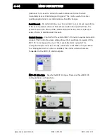
Страница 68: ...eads directly to the MCP 05 manual control screen The MCP 05 manual control button is shown below Propagate alarms Control for the external MCP 05 device consumes two alarm signals Enabling this option causes the state of the consumed alarm signals selected by Control Sources to be sent to the MCP 05 alarm outputs These signals function normally on the MCP 05 outputs with the following exceptions ...

Страница 69: ...rvo Center state and the sensor s retract Specify a value of zero to disable seek timeouts Control Sources Control for the external MCP 05 device requires two alarm signals The Control Sources setting allows the A and B alarm signals of the MCP 05 to be mapped to any of the 4 available alarm outputs The configured output must be correctly connected to the MCP 05 input When the Propagate Alarms opt...

Страница 70: ... the motor 1 or 2 image selects the respective sensor positioner retract direction Reverse the polarity if the drive moves the wrong direction during a Servo Center operation Seek Polarity The polarity button located above the sensor images selects the web seek direction Reverse the seek polarity if the sensor moves the wrong direction when the system is placed in Automatic Press ACCEPT to save ch...

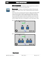
Страница 71: ... control The manual controls provide sensor positioner jogging functionality similar to the controls found on the MCP 05 control unit The MCP 05 manual control screen appearance varies slightly depending on the active sensor mode and the MCP 05 type that has been configured An example of the single and dual drive manual control screens are shown here The sensor signal bar graphs that appear are de...

Страница 72: ...ek operation is initiated Seek operations vary depending on the configured MCP 05 type In all cases it is recommended that non relevant sensor modes be disabled to avoid confusion MCP 05 types and their seek behavior is as follows 1 drive 1 sensor Seeks are allowed using S1 or S2 but not center guiding 1 drive 2 sensors Seeks are allowed using S1 S2 and S1 S2 center guiding modes Center guiding se...

Страница 73: ...ions so a transition from Servo Center to Automatic regardless of the command source will initiate seek operations The same is true for the retract command which is sent on any transition to the Servo Center mode MCP 05 Operation in Networked Systems If multiple MCP 05s are used in a network and the controlling Operator Interface is configured in linked mode Automatic Manual and Servo Center comma...

Страница 74: ...e Jogs while in Manual and Servo Center modes and RGPC functions while in Automatic mode Sensor selection is allowed in Manual and Servo Center modes only Sensor selection must be momentary commands 0 LOW 1 HIGH IGNORE Note To ensure that a command is properly executed all pertinent inputs for each command must be switched high or low within 20 mS of each other and maintained for at least 30 mS WA...

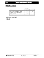
Страница 75: ...ATRIX www maxcessintl com FIFE 500 XL MI 2 267 1 D Digital Output Matrix OUTPUTS STATUS D C B A LOSS OF NULL AUTOMATIC MODE 1 CENTERED SERVO CENTER MODE 1 MOTOR BLOCKED 1 POWER OK 1 Digital outputs are active low 1 ACTIVE IGNORE ...

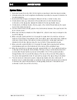
Страница 76: ... two buttons are as follows In Automatic mode the buttons adjust the Guide Point In Manual and Servo Center modes the buttons provide jog functions unless jogs have been disabled in the Control Options menu for one or both of these operation modes 9 When using the optional RGPC 50 F to adjust the Guide Point pressing both buttons simultaneously will reset the Guide Point to the center of the avail...

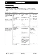
Страница 77: ...ensor Setup Actuator is unstable in Automatic mode System Gain set too high or Cable connectors are loose or Sensor Calibration is not correct Decrease the System Gain Tighten all cable connectors Perform Sensor Setup 1X 1 6 System Gain or 3X 1 6 System Gain 1X 1 7 Sensor Setup Actuator moves the wrong direction in Automatic mode Guide Polarity is incorrect or Incorrect sensor mode selected or Sen...

Страница 78: ... Gain 2X 1 6 Servo Center Gain Actuator is unstable in Servo Center mode Servo Center Gain is set too high Decrease the Servo Center Gain 2X 1 6 Servo Center Gain Actuator moves to either end of the stroke in Servo Center mode Servo Center Polarity is set incorrectly Select MANUAL mode then change the Servo Center Polarity Guide Settings 1X 2 1 Servo Center Polarity ...

Страница 79: ...rvice Requests and Replacement Parts When ordering replacement parts please indicate where possible part number drawing number and model description To request service or to get replacement parts contact one of the addresses listed below Maxcess 222 West Memorial Rd Oklahoma City OK 73114 USA Phone 1 405 755 1600 Fax 1 405 755 8425 Web www maxcessintl com Fife Tidland GmbH Max Planck Strasse 8 657...

Страница 80: ...3 sales maxcess eu www maxcess eu CHINA Tel 86 756 881 9398 Fax 86 756 881 9393 info maxcessintl com cn www maxcessintl com cn INDIA Tel 91 22 27602633 Fax 91 22 27602634 india maxcessintl com www maxcess in JAPAN Tel 81 43 421 1622 Fax 81 43 421 2895 japan maxcessintl com www maxcess jp KOREA TAIWAN AND SE ASIA Tel 65 9620 3883 Fax 65 6235 4818 asia maxcessintl com 2013 Maxcess ...

Отзывы: