background image

34

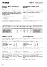
CONSIGLI PRATICI DI INSTALLAZIONE

Posizionamento

-  Osservare scrupolosamente gli spazi di rispetto indicati a catalogo.
- Verifi care che non vi siano ostruzioni sull’aspirazione della batteria 

alettata e sulla mandata dei ventilatori del condensatore remoto ad 
aria collegato all'unità.

-  Posizionare l’unità in modo da rendere minimo l’impatto ambientale 

(emissione sonora, integrazione con le strutture presenti, ecc.).

Collegamenti elettrici

- Consultare sempre lo schema elettrico incluso nel quaderno 


tecnico, ove sono sempre riportate tutte le istruzioni necessarie 
per effettuare i collegamenti elettrici.

-  Dare tensione all’unità (chiudendo il sezionatore) almeno 12 ore 

prima dell’avviamento, per permettere l’alimentazione delle resi-
stenze del carter. Non togliere tensione alle resistenze durante i 
brevi periodi di fermata dell’unità.

-  Prima di aprire il sezionatore fermare l’unità agendo sugli  appositi 

interruttori di marcia, o in assenza sul comando a distanza.

- Prima di accedere alle parti interne dell’unità, togliere tensione 

aprendo il sezionatore generale.

-  É vivamente raccomandata l’installazione di un interruttore ma-

gnetotermico a protezione della linea elettrica di alimentazione (a 
cura dell’installatore).

-  Collegamenti elettrici da effettuare:
  ◊ Cavo di potenza tri terra;
  ◊ Consenso esterno;
  ◊ Riporto allarme a distanza.

Collegamenti idraulici

- Sfi atare accuratamente l’impianto idraulico, a pompe spente, 

agendo sulle valvoline di sfi ato. Questa procedura è particolar-
mente importante in quanto anche piccole bolle d’aria possono 
causare il congelamento dell’evaporatore.

- Installare sempre un fi ltro a rete metallica sull'ingresso dell'unità 

a protezione dello scambiatore a piastre.

-  Realizzare il circuito idraulico includendo i componenti indicati negli 

schemi raccomandati (vaso di espansione, serbatoio d’accumulo, 
valvole di sfi ato, valvole di intercettazione, valvola di taratura, giunti 
antivibranti, ecc.).

Avviamento e manutenzione

-  Attenersi scrupolosamente a quanto indicato nel manuale di uso e 

manutenzione. Tali operazioni devono comunque essere effettuate 
da personale qualifi cato.

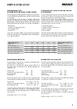
INSTALLATION RECOMMENDATIONS

Location

-  Strictly allow clearances as indicated in the catalogue.
-  Ensure there are no obstructions on the air suction and discharge 

side of the condenser fan air remote connected to the unit.

- Locate the unit in order to be compatible with environmental 

requirements (sound level, integration into the site, etc.).

Electrical connections

-  Check the wiring diagram enclosed with the unit, in wich are always 

present all the instructions necessary to the electrical connections.

-  Supply the unit at least 12 hours before start-up, in order to turn 

crankcase heaters on. Do not disconnect electrical supply during 
temporary stop periods (i.e. week-ends).

- Before opening the main switch, stop the unit by acting on the 

suitable running switches or, if lacking, on the remote control.

-  Before servicing the inner components, disconnect electrical supply 

by opening the main switch.

- The electrical supply line must be equipped with an automatic 

circuit breaker (to be provided by the installer).

-  Electrical connections to be done:
 

 Three-wire power cable + neutral cable + ground cable;


 External interlock;


 Remote alarm signalling.

Hydraulic connections

-  Carefully vent the system, with pump turned off, by acting on the 

vent valves. this procedure is fundamental: little air bubbles can 
freeze the evaporator causing the general failure of the system.

-  Always install a metallic 

fi

 lter on the unit inlet in order to protect 

the plate exchanger. 

-  Install the hydraulic circuit including all the components indicated 

in the recommended hydraulic circuit diagrams (expansion vessel, 
storage tank, vent valves, balancing valve, shut off valves 

fl

 exible 

connections, etc.).

Start up and maintenance operations

-  Strictly follow what reported in use and maintenance manual.  All 

these operations must be carried on by trained personnel only.

Содержание HMV-A 0104

Страница 1: ...T UMLAUFENDER SCROLL VERDICHTERN VON 5 kW BIS 42 kW GROUPES DE PRODUCTION D EAU GLACÉE A CONDENSATION À EAU ET POMPES À CHALEURPOURCONDENSATIONÀDISTANCE AVEC COMPRESSEURS ROTATIF SCROLL DE 5 kW À 42 kW A I R C O N D I T I O N I N G F1 Serie Series Serie Série Serie Emissione Edition Ausga beIssue Emisión HMV A 0104 0142 07 14 Catalogo Catalogue Katalog Brochure Catálogo Sostituisce Superseedes Ers...

Страница 2: ...27 Electrical diagrams 28 33 Installation recommendations 34 INDEX Seite Allgemeines 5 Bauvarianten 5 Konstruktionsmerkmale 5 7 Lose mitgelieferten Zubehöre 7 Technische Angaben 10 11 Elektrische Daten 10 11 Kälteleistungen 12 13 Heizleistungen 14 15 Wärmetauscher Druckverlust e des hydraulischen Kreislaufs 16 Gesamtestatischen Pressung der Umlaufpumpe 16 Korrekturkoeffizienten für Verschmutzungsfa...

Страница 3: ...ircuito realizzato in tubo di rame include filtro disidratatore bidirezionale valvole d espansione valvole di ritegno valvola di inversione a quattro vie presso stato di alta a riarmo manuale pressostato di bassa a riarmo automatico 0124 0142 e indicatore di liquido ed umidità 0124 0142 GENERAL DESCRIPTION Water cooled liquid chiller units for remote condenser for indoor installation The range con...

Страница 4: ... Flüssigkeit und Feuchtigkeits anzeiger 0124 0142 DESCRIPTION GÉNÉRALE Groupe de producion d eau glacée a condensation remote pour installation à l intérieur La gamme est composée de 14 modèles d une puissance de 4 jusqu à 42 kW DIFFÉRENTES VERSIONS HMV A froid seul HMV A SP froid seul avec ballon tampon et pompe HMV A H pompe à chaleur réversible HMV A H SP pompe à chaleur réversible avec ballon ...

Страница 5: ...i controllo e di supervisione centralizzati AG Antivibranti in gomma da inserire alla base dell unità per smorzare eventuali vibrazioni dovute al tipo di pavimento ove la macchina è installata Water circuit The circuit in copper tubing includes water differential pressure switch and manual air release valve HMV A H SP Version Refrigerant circuit The circuit in copper tubing includes bi directional...

Страница 6: ...n dämpfen die durch den Fussbodentyp am Maschinenstandort bedingt sind Circuit hydraulique Le circuit réalisé en tuyau de cuivre inclut pressostat différentiel eau et purge l air manuel Versions HMV A H SP Circuit frigorifique Le circuit réalisé en tuyau de cuivre inclut filtredéshydrateurbi directionnel soupaped expansion soupape de retenue soupape d inversion à quatre voies pressostat de haute pr...

Страница 7: ...ICAL DATA MODELLI 0104 0105 0106 0107 0109 0110 0112 MODEL Massima potenza assorbita kW 1 7 2 2 2 5 3 6 4 0 4 4 5 2 Maximun absorbed power 1 9 2 4 2 7 3 8 4 2 4 6 5 5 Corrente max allo spunto A 37 43 62 62 79 86 58 Maximun starting current 38 44 63 63 80 87 60 Corrente massima assorbita A 7 0 9 0 11 12 15 18 8 0 Full load current 8 0 10 12 13 16 19 11 Pot nomin motore pompa kW 0 20 0 21 0 30 Pump ...

Страница 8: ...ECTRICAL DATA MODELLI 0115 0117 0120 0124 0129 0134 0142 MODEL Massima potenza assorbita kW 6 2 7 2 8 5 9 4 11 2 13 1 16 0 Maximun absorbed power 6 5 7 5 8 8 10 0 11 8 13 7 16 8 Corrente max allo spunto A 61 58 74 142 147 142 142 Maximun starting current 63 60 76 144 149 144 144 Corrente massima assorbita A 10 10 12 23 29 30 30 Full load current 13 13 15 25 31 32 32 Pot nomin motore pompa kW 0 30 ...

Страница 9: ...me d eau condenseur Schalldruckpegel DIN 1 dB A 43 5 43 5 43 5 43 5 44 5 46 5 46 5 Pression sonore DIN 1 Schalldruckpegel ISO 2 dB A 36 5 36 5 36 5 36 5 37 5 39 5 39 5 Pression sonore ISO 2 Liefergewicht kg 74 75 77 81 84 86 87 Poids a l expedition Anschlüsse Connexions Sauglinie Ø mm 12 12 12 12 12 12 16 Ligne d aspiration Flüssigkeitslinie Ø mm 10 10 10 10 10 10 12 Ligne du liquide SP Ausführung...

Страница 10: ...ondenseur Schalldruckpegel DIN 1 dB A 47 5 48 5 50 5 50 5 50 5 51 5 51 5ww Pression sonore DIN 1 Schalldruckpegel ISO 2 dB A 40 5 41 5 43 5 43 5 43 5 44 5 44 5 Pression sonore ISO 2 Liefergewicht kg 89 91 93 183 189 195 206 Poids a l expedition Anschlüsse Connexions Sauglinie Ø mm 16 16 16 22 22 22 22 Ligne d aspiration Flüssigkeitslinie Ø mm 12 12 12 12 12 12 16 Ligne du liquide SP Ausführung Ver...

Страница 11: ...6 1 9 6 2 2 1 5 8 2 3 8 7 6 1 5 7 2 1 7 6 8 1 9 6 4 2 1 6 0 2 3 9 7 8 1 5 7 5 1 7 7 1 1 9 6 6 2 1 6 2 2 3 10 8 1 1 5 7 7 1 7 7 3 1 9 6 9 2 1 6 4 2 3 0107 5 8 1 2 2 7 7 2 4 7 3 2 7 6 8 3 0 6 3 3 3 6 8 4 2 2 8 0 2 4 7 5 2 7 7 1 3 0 6 6 3 3 7 8 7 2 2 8 2 2 4 7 8 2 7 7 3 3 0 6 8 3 3 8 8 9 2 2 8 5 2 4 8 0 2 7 7 6 3 0 7 0 3 3 9 9 2 2 2 8 8 2 4 8 3 2 7 7 8 3 0 7 3 3 3 10 9 5 2 2 9 1 2 4 8 6 2 7 8 1 3 0 7...

Страница 12: ... 24 6 5 1 23 3 5 7 22 0 6 4 20 7 7 1 19 3 7 9 9 25 4 5 1 24 1 5 7 22 8 6 4 21 4 7 1 19 9 7 9 10 26 2 5 2 24 9 5 8 23 5 6 4 22 1 7 1 20 6 7 9 0124 5 27 5 5 7 25 9 6 3 24 3 7 0 22 6 7 8 20 8 8 7 6 28 4 5 7 26 7 6 3 25 1 7 0 23 3 7 8 21 5 8 7 7 29 3 5 7 27 6 6 3 25 9 7 0 24 1 7 8 22 2 8 7 8 30 3 5 8 28 5 6 4 26 7 7 1 24 9 7 8 22 9 8 7 9 31 2 5 8 29 4 6 4 27 6 7 1 25 7 7 9 23 7 8 7 10 32 2 5 9 30 4 6 ...

Страница 13: ... kWe kWt kWe kWt kWe 0104 5 6 0 1 2 5 4 1 3 4 6 1 4 0 6 9 1 3 6 2 1 4 5 1 1 5 5 8 0 1 3 7 3 1 4 6 4 1 5 10 9 2 1 3 8 8 1 4 8 5 1 6 0105 5 6 2 1 6 5 9 1 7 5 6 1 8 0 7 0 1 6 6 7 1 8 6 4 1 9 5 8 0 1 7 7 7 1 8 7 4 2 0 10 9 1 1 7 8 8 1 8 8 5 2 0 0106 5 7 5 1 9 7 4 2 1 7 3 2 4 0 8 6 2 0 8 4 2 2 8 2 2 4 5 9 8 2 0 9 6 2 2 9 3 2 4 10 11 3 2 0 10 9 2 2 10 5 2 4 0107 5 8 6 2 2 8 5 2 4 8 3 2 7 0 9 8 2 2 9 6 2...

Страница 14: ...4 5 16 7 4 9 16 4 5 4 0 19 4 4 5 18 9 5 0 18 5 5 5 5 22 2 4 5 21 6 5 0 21 0 5 5 10 25 4 4 5 24 6 5 0 23 8 5 5 0117 5 20 1 5 3 19 8 5 8 19 5 6 4 0 23 0 5 3 22 5 5 9 22 0 6 5 5 26 4 5 3 25 7 5 9 24 9 6 5 10 30 2 5 3 29 3 5 9 28 2 6 5 0120 5 23 8 6 3 23 4 6 9 23 0 7 6 0 27 2 6 3 26 5 7 0 25 9 7 7 5 31 1 6 4 30 2 7 0 29 3 7 7 10 35 7 6 4 34 5 7 0 33 3 7 8 0124 5 28 3 6 5 27 5 7 3 26 6 8 3 0 32 5 6 5 3...

Страница 15: ...ltwasser von 12 bis 7 C Verflussigungstemperatur 50 C berechnen Kälteleistung 12 1 kW Wasserdurchfluß 12 1x860 5 3600 0 58 l s Total Pressung der Pumpe 211 kPa Einheit Druckverluste des hydraulischen Kreislaufs 31 kPa Max externe Pressung der Pumpe 211 31 180 kPa CIRCULATION PUMP AVAILABLE HEAD PRESSURE CALCULATION EXAMPLE The available pump head pressure can be obtained as follows considering a H...

Страница 16: ... temperature Minima temperatura dell acqua refrigerata con l impiego di glicole C 8 Minimun chilled water outlet temperature with glycol mixture Max pressione di esercizio lato acqua kPa 1000 Max operating pressure water side KORREKTURKOEFFIZIENTEN FÜR VERSCHMUTZUNGSFAKTOREN COEFFICIENTS CORRECTEURS POUR FACTEURS D ENCRASSEMENTS f1 Korrekturfaktoren für Kälteleistung bzw Verflüssigerleistung fp1 K...

Страница 17: ...manometer Manomètre eau MP Elettropompa Electrical pump Elektrische pumpe Pompe electrique PD Pressostato differenziale Differential pressure Switch Differenzdruckscalter Pressostat differentiel RF Rubinetti frigoriferi Shut off valve refrigerators Absperrventil Kühlschränke Réfrigérateurs de robinet SC Scarico acqua Water drain Wasser Entladen Vidange eau SF Indicatore di liquido umiditá 0124 014...

Страница 18: ...zdruckscalter Pressostat differentiel RCV Valvola di inversione a 4 vie 4 Way valve Vierwege umschaltventil Vanne 4 voies RF Rubinetti frigoriferi Shut off valve refrigerators Absperrventil Kühlschränke Réfrigérateurs de robinet SC Scarico acqua Water drain Wasser Entladen Vidange eau SF Indicatore di liquido umidita 0124 0142 Liquid moisture ind Sigth Glass 0124 0142 Flüssig feuchtigkeit Schaugla...

Страница 19: ... 0 kPa Con l aggiunta del 20 di glicole tali grandezze assumeranno i seguenti valori facendo uso dei coefficienti riportati in tabella Resa frigorifera 12 1 x 0 950 11 5 kW Potenza assorbita compressore 4 3 x 0 995 4 28 kW Portata acqua 0 58 x 1 04 0 60 l s Dallacurvadelleperditedicaricosiricavalaperditacorrispondente al nuovo valore della portata 0 60 l s 33 0 kPa La perdita di carico corretta re...

Страница 20: ...sor Leistungsaufnahme 4 3 kW Wasserdurchfluß 0 58 l s Druckverlust 31 0 kPa Mit einem Zusatz von 20 Glykol und unter Verwendung der obenangeführtenKoeffizienten ändernsichdieseWertewiefolgt Kälteleistung 12 1 x 0 950 11 5 kW Compressor Leistungsaufnahme 4 3 x 0 995 4 28 kW Mischungsdurchfluß 0 58 x 1 04 0 60 l s Von der Druckverlust Kurve kann der dem neuen Durchflußwert entsprechendeDruckverlust ...

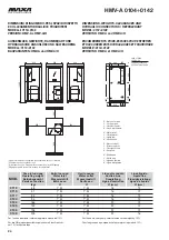
Страница 21: ... 75 800 550 1200 500 550 500 200 550 DIMENSIONI DI INGOMBRO PESI SPAZI DI RISPETTO E COLLEGAMENTI IDRAULICI E FRIGORIFERI MODELLI 0104 0110 VERSIONI HMV A HMV A H AUSSENMAßE GEWICHTE RAUMBEDARF UND HYDRAULISCHE ANSCHLÜßE UND KÄLTESCHEMA MODELL 0104 0110 BAUVARIANTEN HMV A HMV A H DIMENSIONS WEIGHTS CLEARANCES AND HYDRAULIC CONNECTIONS REFRIGERANT MODELL 0104 0110 VERSIONS HMV A HMV A H ENCOMBREMEN...

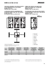
Страница 22: ... A SP HMV A H SP DIMENSIONS WEIGHTS CLEARANCES AND HYDRAULIC CONNECTIONS REFRIGERANT MODELL 0104 0110 VERSIONS HMV A SP HMV A H SP ENCOMBREMENTS POIDS ESPACES POUR ENTRETIEN ET RACCORDEMENTS HYDRAULIQUES ET FRIGORIFIQUE MODÈLE 0104 0110 VERSIONS HMV A SP HMV A H SP X Ingresso acqua Y Uscita acqua J Linea del liquido K Linea di mandata X Water Inlet Y Outlet water J Liquid line K Suction line X Was...

Страница 23: ...reintritt Entrée eau Uscita acqua Water outlet Wasseraustritt Sortie eau Linea di mandata Suction Line Saugleitung Ligne d aspiration Linea liquido Liquid line Flussigkeisleitung Ligne de liquide kg Ø Ø Ø mm Ø mm 0112 88 1 M 1 M 16 12 0115 91 1 M 1 M 16 12 0117 93 1 M 1 M 16 12 0120 95 1 M 1 M 16 12 0124 186 1 M 1 M 22 12 0129 192 1 M 1 M 22 12 0134 198 1 M 1 M 22 12 0142 209 1 M 1 M 22 16 K Y J X...

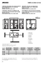
Страница 24: ...s en fonction Entrata acqua Water inlet Wassereintritt Entrée eau Uscita acqua Water outlet Wasseraustritt Sortie eau Linea di mandata Suction Line Saugleitung Ligne d aspiration Linea liquido Liquid line Flussigkeisleitung Ligne de liquide kg Ø Ø Ø mm Ø mm 0112 SP 161 1 M 1 M 16 12 0115 SP 162 1 M 1 M 16 12 0117 SP 165 1 M 1 M 16 12 0120 SP 167 1 M 1 M 16 12 K J X Y EW 60 135 93 80 80 80 515 470 ...

Страница 25: ...n fonction Entrata acqua Water inlet Wassereintritt Entrée eau Uscita acqua Water outlet Wasseraustritt Sortie eau Linea di mandata Suction Line Saugleitung Ligne d aspiration Linea liquido Liquid line Flussigkeisleitung Ligne de liquide kg Ø Ø Ø mm Ø mm 0124 SP 415 1 M 1 M 22 12 0129 SP 421 1 M 1 M 22 12 0134 SP 427 1 M 1 M 22 12 0142 SP 438 1 M 1 M 22 16 Z Y J K EW 60 135 80 80 515 470 250 220 4...

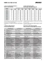
Страница 26: ...KING PROBE WASSERTEMP FÜHLER SONDE DU TRAVAIL ST2 SONDA ANTIGELO ANTIFREEZE PROBE FROSTSCHUTZFÜHLER SONDE ANTIGEL ST3 SONDA TEMPERATURA H TEMPERATURE PROBE H TEMPERATUR FÜHLER H SONDE TEMPERATURE H TR TRASFORMATORE TRANSFORMER TRAFO TRASFORMATEUR YVI VALVOLA INVERSIONE DI CICLO H CYCLE REVERSAL VALVE CIRCUIT H UMSCHALTUNGSVENTIL H VANNE D INVERSION DE CICLE H YVW VALVOLA SOLENOIDE ACQUA WATER SOLE...

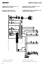
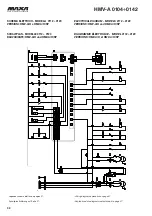
Страница 27: ...ARIANTE HMV A und HMV A SP ELECTRICAL DIAGRAM MODELS 0104 0110 VERSIONS HMV A and HMV A SP DIAGRAMME ÉLECTRIQUE MODEL 0104 0110 VERSIONS HMV A et HMV A SP Legenda schema elettrico a pagina 27 Schaltplan Erklärung auf Seite 27 Wiring diagram explanation on page 27 Explication de le diagramme électrique à la page 27 ...

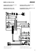
Страница 28: ...ARIANTE HMV A und HMV A SP ELECTRICAL DIAGRAM MODELS 0112 0120 VERSIONS HMV A and HMV A SP DIAGRAMME ÉLECTRIQUE MODEL 0112 0120 VERSIONS HMV A et HMV A SP Legenda schema elettrico a pagina 27 Schaltplan Erklärung auf Seite 27 Wiring diagram explanation on page 27 Explication de le diagramme électrique à la page 27 ...

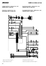
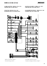
Страница 29: ...ARIANTE HMV A und HMV A SP ELECTRICAL DIAGRAM MODELS 0124 0142 VERSIONS HMV A and HMV A SP DIAGRAMME ÉLECTRIQUE MODEL 0124 0142 VERSIONS HMV A et HMV A SP Legenda schema elettrico a pagina 27 Schaltplan Erklärung auf Seite 27 Wiring diagram explanation on page 27 Explication de le diagramme électrique à la page 27 ...

Страница 30: ...NTE HMV A H und HMV A H SP ELECTRICAL DIAGRAM MODELS 0104 0110 VERSIONS HMV A H and HMV A H SP DIAGRAMME ÉLECTRIQUE MODEL 0104 0110 VERSIONS HMV A H et HMV A H SP Legenda schema elettrico a pagina 27 Schaltplan Erklärung auf Seite 27 Wiring diagram explanation on page 27 Explication de le diagramme électrique à la page 27 ...

Страница 31: ...age 27 Explication de le diagramme électrique à la page 27 SCHEMA ELETTRICO MODELLI 0112 0120 VERSIONI HMV A H e HMV A H SP SCHALTPLAN MODELLE 0112 0120 BAUVARIANTE HMV A H und HMV A H SP ELECTRICAL DIAGRAM MODELS 0112 0120 VERSIONS HMV A H and HMV A H SP DIAGRAMME ÉLECTRIQUE MODEL 0112 0120 VERSIONS HMV A H et HMV A H SP ...

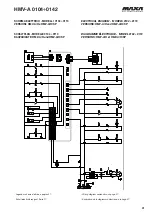
Страница 32: ...NTE HMV A H und HMV A H SP ELECTRICAL DIAGRAM MODELS 0124 0142 VERSIONS HMV A H and HMV A H SP DIAGRAMME ÉLECTRIQUE MODEL 0124 0142 VERSIONS HMV A H et HMV A H SP Legenda schema elettrico a pagina 27 Schaltplan Erklärung auf Seite 27 Wiring diagram explanation on page 27 Explication de le diagramme électrique à la page 27 ...

Страница 33: ...rcettazione valvoladitaratura giunti antivibranti ecc Avviamento e manutenzione Attenersi scrupolosamente a quanto indicato nel manuale di uso e manutenzione Talioperazionidevonocomunqueessereeffettuate da personale qualificato INSTALLATION RECOMMENDATIONS Location Strictly allow clearances as indicated in the catalogue Ensure there are no obstructions on the air suction and discharge side of the ...

Страница 34: ...e en place Observer scrupuleusement les espaces pour l entretien tels qu indiqués précédemment Vérifier qu il n existe aucune obstruction sur l aspiration de l air au travers de la batterie ailettée et sur le refoulement des ventilateurs condenseur à air distant connecté à l unité Positionner l unité de manière à n affecter qu au minimum l environ nement émission sonore intégration sur le site etc...

Страница 35: ...ungen ohne Ankündigung vor The data indicated in this manual are purely indicative The manufacturer reserves the right to modify the data whenever it is considered necessary Les données reportées dans la présente documentation ne sont qu ndicatives Le constructeur se réserve la faculté d apporter à tout moment toutes les modifications qu il jugera nécessaires I dati riportati nella presente docume...

Отзывы: