background image


Rules Manager/Device Explorer


V4.5


Page 5-18 


5.3.1. 

Tree View 

The 

Tree View

 pane on the left side displays a list of connected devices, and for 

each device, a hierarchy of video feeds per device, MSF per video feed, and 
detection zones (ROI) set for each MSF. 

The Tree View shows all the units connected to the same Cortex server. 

To connect to a VDU device that is defined as a standalone device: 


In the Device Explorer view double click on the device

The device Tree View with its cameras will open in the Rules Manager view.  


5.3.2. 

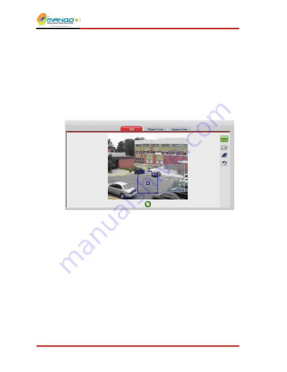
Alarm Geometry Pane 


F

IGURE 

22:


A

LARM 

G

EOMETRY 

P

ANE


The Alarm Geometry pane comprises the following parts: 


Live Video 

- shows the selected video feed. A Play/Pause button is located 

under the video frame. When pressed, the button pauses the video in the Rules 
Manager to capture a subject and use its image to facilitate setup. 


Alarm Geometry Tabs

 – located on top of the video display (displayed 

when an alarm is highlighted). 


Drawing Toolbar

 – located to the right of the video display and displayed 

when an alarm is highlighted. The toolbar's content varies according to the 
Alarm Geometry Tab that is highlighted. 


Содержание iSense

Страница 1: ...V4 5 iSense User Guide Version 4 5 ...

Страница 2: ...ed that the above copyright notice and this paragraph are duplicated in all such forms and that any documentation advertising materials and other materials related to such distribution and use acknowledge that the software was developed by MATE Intelligent Video Ltd THIS SOFTWARE IS PROVIDED AS IS AND WITHOUT ANY EXPRESS OR IMPLIED WARRANTIES INCLUDING WITHOUT LIMITATION THE IMPLIED WARRANTIES OF ...

Страница 3: ... 3 System Setup 3 1 3 1 In the Package 3 1 3 2 Operating System Requirements Cortex 3 1 3 3 Camera Installation 3 2 3 4 Installing the Hardware 3 2 3 5 LED Display 3 3 3 6 Installing the Cortex Software 3 4 3 6 1 Installing NET Framework 3 4 3 6 2 Cortex Installation 3 4 3 7 Un Installing the Software 3 5 4 Getting Started 4 1 4 1 Initial Use of the Application 4 1 4 2 StartUp Application 4 2 4 2 ...

Страница 4: ...SF BW only 5 21 5 4 3 Activating Deactivating a Single MSF 5 22 5 4 4 Activating Deactivating Multiple MSFs 5 22 5 4 5 Deleting an MSF 5 22 5 4 6 Renaming an MSF 5 22 5 4 7 Copy Paste an MSF 5 22 5 4 8 Exporting an MSF 5 23 5 4 9 Importing an MSF 5 23 5 5 Working with Alarm Geometries 5 23 5 5 1 ROI Tab for Detection Zone Geometry 5 24 5 5 2 Object Sizes Tab 5 24 5 5 3 Classification Tab 5 24 5 5 ...

Страница 5: ...ce 7 1 7 1 Accessing DB Maintenance 7 1 7 2 Action Type and Action Range 7 2 7 3 Deleting a Camera 7 2 7 4 Deleting a Device 7 3 7 5 Renaming a Camera 7 3 7 6 Tools 7 3 8 Relays 8 1 8 1 Relays Setup 8 1 9 Appendix 9 1 9 1 Hardware Specifications 9 1 9 2 List of WAN Port Numbers and Applications 9 2 10 Index 10 1 ...

Страница 6: ...5 10 Figure 13 De interlaced Image 5 10 Figure 14 I O Settings Tab Trigger 5 11 Figure 15 I O Settings Tab iSense 5 11 Figure 16 External Interfaces tab Trigger 5 13 Figure 17 External Interfaces tab iSense 5 13 Figure 18 IP Video Source Settings Tab 5 15 Figure 19 Date Time settings tab 5 16 Figure 20 Additional Settings tab 5 16 Figure 21 Rules Manager 5 17 Figure 22 Alarm Geometry Pane 5 18 Fig...

Страница 7: ...Table of Contents V4 5 Page vii Figure 32 CountWatch DB Writer 6 2 Figure 33 Add VDU 6 3 Figure 34 DB Maintenance Utility 7 2 ...

Страница 8: ......

Страница 9: ...o a common database Access to the counting data is done via one or more web based tools run from standard browsers 1 1 ABOUT THIS GUIDE This guide is divided into the following sections 1 Overview A general overview of iSense 2 System Setup Procedure for setting up the hardware and software 3 Getting Started Running the software 4 Rules Manager Device Explorer Application for the configuration of ...

Страница 10: ......

Страница 11: ...ies to count people or cars entering or exiting a region of interest The field of VCA is also known as Computer Vision 2 2 ARCHITECTURE iSense is comprised of different modules each fulfilling a specific task The system is scalable from a single machine up to a large network analyzing a large number of video cameras The architecture remains the same although the component parts may end up residing...

Страница 12: ...splaying live video images with video tracking overlay The installation includes one Cortex Viewer installed on the same machine for local operation The Cortex Viewer is pre configured to operate with the local Cortex Server installed on the same machine local IP Address 127 0 0 1 2 3 6 Rules Manager Device Explorer The Rules Manager program defines and manages rule sets that specify the type shap...

Страница 13: ...ement of all the devices is done from a single centralized location 3 1 IN THE PACKAGE The iSense product package includes iSense device with power supply auto select 110V 220V to 12V Installation CD with the Cortex software Three 8 pin connectors Dome Camera optional purchase 3 2 OPERATING SYSTEM REQUIREMENTS CORTEX Software Microsoft Windows Server 2003 Standard Edition SP2 32 bit NET Framework ...

Страница 14: ...f the lens to the floor should be 3 m or 10 ft and the camera should point vertically downwards see diagram below 2 Accuracy can be reduced by reflections from the floor and by hard shadows Position camera and optional lighting sources to minimize these factors 3 Make sure the people to be counted are fully visible in the image even when traveling near the edges of the zone Increase the height of ...

Страница 15: ...n Socket 1 located on the front panel of the iSense Use BNC connectors 3 Connect the power supply to the socket located on the back panel of the iSense see Fig 3 Make sure the Power Supply itself is located close to the iSense Note See the Appendix on page 9 1 for the technical specifications of all connections 3 5 LED DISPLAY Once the power is connected the LED Panel displays the following inform...

Страница 16: ...install the basic support for files and Direct Show Analog video capture device as well as support for Intellex Axis and Sony Custom to selectively decide which support to add in addition to the basic support for files and Direct Show Click Next to continue 4 At the Event Media Setup Wizard Click Next to continue 5 Either accept the default location for the installation of the program files or bro...

Страница 17: ... may result in some components of the application not functioning as intended 3 7 UN INSTALLING THE SOFTWARE To uninstall the Cortex software 1 Click Start Settings Control Panel Add or Remove Programs find Cortex in the list and select it click the Change Remove button 2 In the Installation Wizard that opens choose Remove to uninstall all the software ...

Страница 18: ......

Страница 19: ...hen running the application for the first time after installation an Application Settings window is opened Click the applications that you are licensed to use If you are running Cortex Watch select Cortex FIGURE 4 APPLICATION SETTINGS After the installation completes after restarting the computer double click on the VCA shortcut placed on the desktop during installation StartUp Application launche...

Страница 20: ... preconfigured WAN IP Address of the Cortex Viewer as the VDU sends video directly to the Cortex Viewer bypassing the Cortex Server application Enter the IP Address and click OK If running no other instance of Cortex Viewer outside the same LAN click Cancel 4 2 STARTUP APPLICATION StartUp Application is an all in one application that performs the following actions Launches all critical software pr...

Страница 21: ...of the buttons is not visible open the Configuration Window Tools Configuration and select the applications to run Restart the StartUp Application for the change to take effect 4 2 1 Interface Language StartUp Application can be optionally configured to display the user interface in another language 1 To change the interface language Click Tool Interface Language and select one of the languages av...

Страница 22: ......

Страница 23: ...cation used to remotely configure Video Detection Units on the network Although Video Detection Units come preset with default settings it is important to change these settings to suit the specific network 5 1 LAUNCHING RULES MANAGER DEVICE EXPLORER 1 Double click the desktop Rules Manager icon The Rules Manager Login window opens 2 The Rules Manager Login window opens Type joker in the User field...

Страница 24: ...Rules Manager Device Explorer V4 5 Page 5 2 FIGURE 7 RULES MANAGER VIEW FIGURE 8 DEVICE EXPLORER VIEW ...

Страница 25: ...plays live video Mapping Display map with camera icon location Tools Connect to Device in Default Cortex Server Connects to Cortex Server Device Explorer click to switch from Rules Manager view to Device Explorer view Settings Change Credential Account change user password Change Interface Language Select language Help About Opens the About Us dialog Rule Manager Help Opens the online help ...

Страница 26: ...Rules Manager Device Explorer V4 5 Page 5 4 5 2 DEVICE EXPLORER VIEW FIGURE 9 RULES MANAGER DEVICE EXPLORER 5 2 1 General Settings Tab FIGURE 10 GENERAL SETTINGS TAB ...

Страница 27: ... Device ID Number Every device in the Cortex network has a unique identifier Enter a number that will be unique to this device make up a number any integer between 1 and 9999 can be entered in this field as long as each device in the same Cortex network has a different number Device s Video Standard PAL or NTSC Network Type Optimize the device to work within a Local Area Network LAN or a Wide Area...

Страница 28: ...ice tree 3 Select the device in the List View of Device Explorer and then click the Select File button to browse for the file in its saved location Click OK to confirm Once the Bin file is selected click the Burn File button and wait for approximately one minute for the process to complete Click OK to confirm 4 Plug in the video cables This process needs to be repeated for each device to be update...

Страница 29: ... 5 2 2 Video Settings Tab FIGURE 11 VIDEO SETTINGS TAB 5 2 2 1 IMAGE PROPERTIES The Image Properties are effective in controlling bandwidth by allowing for the customization of the resolution of the transmitted images as follows Image Size Choose between 4CIF CIF or QCIF ...

Страница 30: ...is taken into account VBR Variable Bit Rate A bit stream of variable bit rate is generated by the VDU The parameters to be used in this case to adjust the performance and behavior of the VDU are Base Quality Average BR and Maximum BR CBR Constant Bit Rate A bit stream of constant bit rate is generated by the VDU The parameters to be used in this case to adjust the performance and behavior of the V...

Страница 31: ...o apply any new settings 5 2 2 3 ANALOG VIDEO OUT The Video Source setting activates the Video Out port select None to disable Video Out When selecting the analog video output select the video source as follows Camera Choose Camera1 or Camera2 as the video source The analog video output is fixed to the camera and appears as a full screen Alarmed Camera The camera that gets an alarm will appear on ...

Страница 32: ...ace artifacts or combing which occur with moving objects in the image When there is a lot of motion in a scene the image may be blurred and objects can be duplicated In order to tell if a camera is interlacing is to rapidly move the camera and see whether objects are duplicated or not The figure below demonstrates this phenomenon FIGURE 12 INTERLACED IMAGE BEFORE FILTER If this occurs check the De...

Страница 33: ...ion of relays and inputs Relay Policy Determines how the output relay is activated when an alarm is triggered on any video feed as follows Idle No activation of the output relay on an alarm must be set to Idle in order to allow manual activation of relays through the Cortex Viewer Pulse Activation of the output relay for an amount of time from 1 300 seconds set by Pulse Duration sec Level Activati...

Страница 34: ...d disabled if Relay Policy is set to Idle Counting H W Switch iSense Determines whether a hardware switch closing the input contacts assigned to a video feed has any effect on counting alarms generated as follows Dry Contact Pulse Duration milliseconds Set the sampling rate of the relay input used in the dependency rule Click the Save button to apply any new settings 5 2 3 2 AUDIO DEVICES Display ...

Страница 35: ...RFACES TAB ISENSE 5 2 4 1 AVC SERVER TRIGGER ONLY The Video Detection Unit e g Trigger NG can be configured optionally to send a video clip of an event to a specific IP Address where an AVC Server resides The AVCS stores the information for browsing and presentation via the Cortex Player Note The AVC Server works only in the T2 NG mode and not in the 2S or 1S modes AVCS must be installed on the AV...

Страница 36: ...a application running on the device can be configured optionally to send metadata to a specific IP address where another Metadata application acting as a client or server resides receiving messages from the VDU using XML over TCP IP The server application is responsible for connection handling and monitoring The Multi Metadata channel configuration allows you to configure and enable multiple metad...

Страница 37: ...VR Alarms Port Trigger only Port Address for sending alarms to the DVR It is recommended to keep the default value Click the Save button to apply any new settings 5 2 5 IP Video Source Settings FIGURE 18 IP VIDEO SOURCE SETTINGS TAB The IP Video Source Settings allows you to choose an IP camera source as an input to the device Consult with a local service representative for information on supporte...

Страница 38: ...or an external NTP server to synchronize all devices to an external time generator Select the checkbox to use the NTP Server Enter the Time Zone difference in minutes from UTC Enter the update frequency in minutes Enter the IP Address of the NTP Server Click Save to apply the settings 5 2 7 Additional Settings Tab FIGURE 20 ADDITIONAL SETTINGS TAB ...

Страница 39: ...FIGURE 21 RULES MANAGER Tree View displays a hierarchy of connected Video Detection Units VDUs video feeds and rule sets known as MSFs for easy access to these elements Alarm Geometry comprises Live Video Display Alarm Geometry Tabs e g ROI Object Size Ignore Zone and a tab sensitive Drawing Toolbar to support drawing of alarm zones object sizes and optional ignore zones on the video window Alarm ...

Страница 40: ...iew with its cameras will open in the Rules Manager view 5 3 2 Alarm Geometry Pane FIGURE 22 ALARM GEOMETRY PANE The Alarm Geometry pane comprises the following parts Live Video shows the selected video feed A Play Pause button is located under the video frame When pressed the button pauses the video in the Rules Manager to capture a subject and use its image to facilitate setup Alarm Geometry Tab...

Страница 41: ...te with somewhat reduced probability of detection Alternatively you may increase sensitivity to High for detecting small or low contrast objects at the expense of a slightly higher false alarm rate 5 3 3 2 ACTIVATE RELAY Activate Relay only appears as an option for alarms set for Trigger NG devices Activating this checkbox for the specified alarm will also activate the alarm relay on the device Th...

Страница 42: ...painted dark blue indicates it is in disabled mode a rubric painted light gray indicates it is in enabled mode By default the Enable All button is selected allowing constant 24 7 alarm generation for each MSF You can disable alarm notifications for a selected MSF by clicking the Disable All button To determine specific days and time for events detection first create an MSF then follow either of th...

Страница 43: ...t 5 4 1 Creating an MSF When you create an MSF it will be assigned a default name based on the camera and feed or file information You can change this default name by clicking the MSF name field and typing a new name over it or you can leave the default name Identical names cannot be assigned for different MSF files per feed To create an MSF 1 Right click on a feed s name field and select Add New ...

Страница 44: ...ive MSF from the popup menu for each MSF A double check appears next to the left of each MSF name field to indicate it is one of the active MSFs Note If a scheduling conflict occurs between an already active MSF and the one being activated an error message will appear showing the time s of the scheduling conflict 5 4 5 Deleting an MSF To avoid clutter on the Tree View pane delete obsolete unusable...

Страница 45: ...he video type size is the same as the export type size 5 5 WORKING WITH ALARM GEOMETRIES Video based detection algorithms analyze a stream of two dimensional video images thereby allowing us to define rules and alarm criteria with high spatial resolution Alarms are geometrically specified in terms of detection zones or object boundaries by object sizes with optional perspective and by optional ign...

Страница 46: ...ct Sizes Tab When you set an alarm it is necessary to set minimum and maximum bounds on the size of subjects to be detected in order to ignore irrelevant subjects and thus avoid false alarms The bounds are set by a pair of concentric rectangles that represents the maximum and minimum sizes horizontal and vertical of a subject you wish to detect You can move the indicators to an image location wher...

Страница 47: ... Select the Maximum rectangle button from the toolbar Two rectangular shapes appear at the center of the frame The external rectangle determines the maximum size of the subject and the internal one determines its minimum size 5 In order to resize the external rectangle horizontally move the mouse pointer over its left or right edges until a two headed arrow appears Then resize the shape by left cl...

Страница 48: ... values defined at one image location will be highly inaccurate at other image locations resulting in lower detection probability and or increased false alarm rate Exact calibration of object size may be tedious and may require information that is not available from the video images only We have introduced a way of working with perspective that is simple yet accurate enough for our robust detectio...

Страница 49: ...tive 1 In the Rules Manager window left click to highlight an alarm 2 Select the Object Sizes tab 3 From the Alarm tab click With Perspective FIGURE 27 PERSPECTIVE Two pairs of rectangular indicators appear one pair for a Near point and the other for a Far Point FIGURE 28 OBJECT SIZES 4 Use the Shift button to move the Near point indicator to the nearest location in the ROI 5 Set the Maximum recta...

Страница 50: ...tion when the subjects enter the zone Some scenarios include a high level of activity that is not related to the desired detection such as a road located far from the zone The ignore zone allows the system to ignore this area and reduce the computational load for the algorithm An ignore zone may encompass a part of a detection zone when the activity inside that part is meant to be ignored Setting ...

Страница 51: ...in the same MSF Change the Sensitivity value on the Alarm tab to High if the detection zone is environmentally quiet image wise and if low contrast subjects need to be detected Alternatively change Sensitivity to Low if the detection zones and the encompassing area are environmentally noisy 5 6 2 Display and Editing Options Right click the alarm name field for the following options Show All ROIs D...

Страница 52: ...Access Watch The Rules Manager application automatically identifies each type of VDU and so only the relevant Alarm Types will be accessible on the sub menu for adding an alarm to an MSF Note All alarms are license dependent 5 7 1 People Counting Description People Counting is used for the real time detection and counting of people in video images converting video data into real time counting info...

Страница 53: ...t whether to expect shopping carts in the scene 6 Click the Start Learning button The Rules Manager application will then go through a two stage process of first learning the background static scene and then learning the average size from people passing Keep the scene clear of people for the first phase the Next button will become enabled once enough of the background has been learned and then hav...

Страница 54: ...ounting bar as required 3 Select the Typical Size tab and adjust the size of the rectangle to match the typical size of a car in the video image 4 On the Alarm tab Select the Car Direction as appropriate Select whether the camera views the scene from the Top or from the Side 5 Click the Start Learning button The Rules Manager application will then go through a process of learning the background st...

Страница 55: ...n is then stored in a single database for later retrieval The DB Writer application can be accessed by clicking the System Tray Icon or via the StartUp Application By default the DB Writer has been set as a Server and the VDUs as Clients Changing the DB Writer to work as a Client and the VDUs to act as Servers also requires manually adding VDUs see Add VDUs on page 6 3 Important Before running thi...

Страница 56: ...e Connect button to establish the connections Leave the default port number of 1977 Clear List Clears the Log View Advanced Application Mode Set as Client or Server Help Opens the online help Connected Devices Displays all of the connected devices VDUs Connection and transfer logging information for these devices are displayed in the Log View Refresh Reestablish connections to all iSense and Count...

Страница 57: ... 5 Page 6 3 6 2 ADD VDUS Only accessible if the application is set as a client Use the dialog to manually add the desired IP addresses of all iSense and Count Watch VDUs in the network and then save and exit FIGURE 33 ADD VDU ...

Страница 58: ......

Страница 59: ...ted with a specific device or camera 7 1 ACCESSING DB MAINTENANCE Double click on the VCA Utilities folder shortcut placed on the desktop during installation and then double click on DBMaintenance Very Important Make sure that the Reporter Manager and DBWriter applications are closed beforehand Failure to close these applications may result in errors within the database itself Enter a valid User N...

Страница 60: ...ase Rename Camera Renames records associated with a particular camera in the database Choose one of the following Action Ranges All Dates Applies the Action Type to all records in the database Range Of Dates Applies the Action Type to records between the From Date and the To Date in the database Up To Date Applies the Action Type to records up to the To Date in the database 7 3 DELETING A CAMERA D...

Страница 61: ...5 RENAMING A CAMERA Renaming a camera will update all records associated with that camera in the database to reflect a new name 1 Select Action Type Rename Camera 2 Select the current Camera Name from the drop down box 3 Type a new name in the New Camera Name textbox 4 Click the Execute button Note This action only affects records already in the database If the camera itself has not been given the...

Страница 62: ...ations with access to the database are closed Reporter Manager DB Writer and Scheduler Manager before restoring a backed up database Note When upgrading the software from a previous version make sure to restore the backed up database before starting to run the new software as restoring a database from a previous backup will overwrite all current data in the database ...

Страница 63: ...en them Note Either Relays 1 and 2 OR Relays 3 and 4 can be operational Because of mutually exclusive configuration settings all the relays cannot function simultaneously 8 1 RELAYS SETUP Hardware For Manual Activation connect to the Relay PINs with an 8 pin connector as follows i The first relay is connected to Relay 1 ii The second relay is connected to Relay 2 For Counting Relays connect to the...

Страница 64: ......

Страница 65: ...audio 3 5 mm Jack UART Two RS232 ports and one RS485 port Onboard Relays Two SPDT Relays and two Solid State Relays Relay Contacts 2 pairs NO COM NC and 2 pairs SSR Alarm Inputs Two Optically isolated inputs Networking TCP IP 10 100 Base T Power Supply Input 12 V DC Operating Temperature to C to F Storage Temperature C to C F to F Operating Humidity 20 to 80 non condensing Storage Humidity 5 to 95...

Страница 66: ...ter 4000 Dedicated Micros 4808 Cortex Viewer 4809 Rules Manager 4810 Cortex Server 5000 Intellex V3 x 5001 Intellex V4 x 6970 Live Video 1984 Device Explorer 1985 7071 7072 7095 7096 8071 50152 Audio In 50153 Audio Out Note For information regarding the creation and use of reports refer to the CW Reports section of the Cortex Server User Guide ...

Страница 67: ... 4 Display and Editing Options 5 29 DVR 5 15 E Enable Relay Output for System Event 5 19 Exporting an MSF 5 23 G General Settings Tab 5 4 Getting Started 4 1 H Hardware and Operating System Requirements 3 1 Hardware Specifications 9 1 I Ignore Zone Tab 5 28 Image Properties 5 7 Importing an MSF 5 23 In the Package 3 1 Indoor Outdoor Selection 5 21 Initial Use of the Application 4 1 Installing NET ...

Страница 68: ...stem Setup 3 1 T The Technology 2 1 Tools 7 3 Tree View 5 18 U Un Installing the Software 3 5 V Video Source 5 5 Video Transmission Settings 5 8 W Working with Alarm Geometries 5 23 Working with MSFs 5 21 Working with Perspective 5 26 Working without Perspective 5 25 ...

Отзывы: