4
/
6
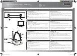
Rear panel has 4 sockets:
TUNER
: Connect the tuner via a 50 ohm coaxial cable.
TRANSMITTER
: Connect the transmitter's "ANT" socket via a 50 ohm
coaxial cable.
DC 12-14V 1A
: External DC power supply. When the coupler is not
connected to transmitter via control cable, this socket needs to be connected
to power supply, and tuner works in general mode. This socket is not used if
the coupler is connected to transmitter via a control cable.
CONTROL
: Control cable socket. If this socket is connected to the "TUNER"
socket of transmitter via a control cable, the coupler will work in dedicated
mode. mAT-50-M coupler comes with a mAT-CI control cable and mAT-50-Y
coupler comes with a mAT-CY control cable.
INSTALLATION
Please select the correct coupler and control cable for your transmitter.
Installation
1.
Please install the tuner firmly, and protect the coaxial cable socket from
water after connecting the coaxial cable.
2.
Connect the antenna and system ground to the corresponding terminals
of the tuner and tighten the screws.
3.
Connect the other end of the coaxial cable to the "TUNER" socket of the
coupler. Please note that only a single feeder can be used between the
tuner and the coupler, no equipment or components should be connect
-ed. The "TUNER" socket of the coupler should not be short circuited,
otherwise the coupler and transmitter may be damaged.
4.
Use another coaxial cable to connect the coupler's "TRANSMITTER"
socket to the transmitter's "ANT" socket.
5.
If you want the tuner to work in dedicated mode, use correct control
cable to connect the coupler's "CONTROL" socket to the transmitter's
"TUNER" socket. If you want the tuner to work in general mode, connect
the coupler's "DC" socket to a 13.8V DC power supply.