Alien ALR-9650, Hardware Setup Manual
The Alien ALR-9650 is an advanced RFID reader that offers seamless inventory management and tracking. To help you maximize its potential, make sure to get your hands on the comprehensive Hardware Setup Manual. Download this essential manual for free from our website and unlock the full potential of your Alien ALR-9650.
Share
Download


Reviews:
No comments
Related manuals for ALR-9650

DISH 500+
Brand: EchoStar Pages: 28

1.0M
Brand: Patriot Pages: 16

AAN X1
Brand: AEG Pages: 10

ProSafe ANT224D10
Brand: NETGEAR Pages: 2

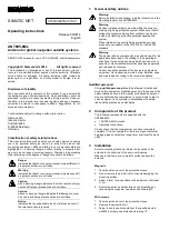
SIMATIC NET ANT897-4MC
Brand: Siemens Pages: 4
SIMATIC NET ANT895-6ML
Brand: Siemens Pages: 2

SIMATIC NET ANT896-4MA
Brand: Siemens Pages: 4

ANT795-4MB
Brand: Siemens Pages: 4

SIMATIC RF615A
Brand: Siemens Pages: 34

ANT795-4MA
Brand: Siemens Pages: 4

7LF4 941-5
Brand: Siemens Pages: 3

SIMATIC NET ANT795-6MT
Brand: Siemens Pages: 60

ANT792-6MN
Brand: Siemens Pages: 32

ANT793-8DK
Brand: Siemens Pages: 46

6GK5795-6MN10-0AA6
Brand: Siemens Pages: 44

ANT793-6DG
Brand: Siemens Pages: 58

J-105-HI-WC
Brand: Wade Pages: 2

6822
Brand: Shively Labs Pages: 78


