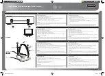
Siemens ANT793-8DK, Compact Operating Instructions
The Siemens ANT793-8DK Compact Operating Instructions manual is now available for free download on manualshive.com. Get step-by-step guidance and valuable information on operating your Siemens ANT793-8DK device. Access the user manual today and optimize your product knowledge quickly and conveniently.
Share
Download


Reviews:
No comments
Related manuals for ANT793-8DK

FAD–1400
Brand: American Communication Systems Pages: 5

75-5AS
Brand: M2 Antenna Systems Pages: 3
Premium STV215
Brand: Bandridge Pages: 2
DTA300
Brand: August Pages: 3

OMNIPRO+
Brand: ANTARION Pages: 16

Manpack
Brand: iNetVu Pages: 22

E002ANT
Brand: Etec Pages: 4

E001ANT
Brand: Etec Pages: 4

ValuLine VHLP Series
Brand: CommScope Pages: 30

Snipe
Brand: SELFSAT Pages: 89

DAT HD Boss 790
Brand: Televes Pages: 4
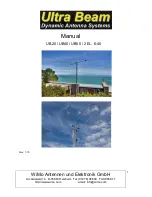
UB20
Brand: Ultra Beam Pages: 11

179823
Brand: Hama Pages: 22

SW3-935
Brand: Panorama Antennas Pages: 2

CP6
Brand: Diamond Antenna Pages: 4

QuadPro
Brand: WaveForm Pages: 16

LABRADOR
Brand: Parsec Technologies Pages: 7

OCEAN M60
Brand: MR Marine Electronics Pages: 2


