M2 Antenna Systems, Inc. 4402 N. Selland Ave. Fresno, CA 93722
Tel: (559) 432-8873 Fax: (559) 432-3059 Web: www.m2inc.com
©2013 M2 Antenna Systems Incoporated
9/13/13
Rev.00
M2 Antenna Systems, Inc.
Model No: 75-5AS
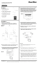
Assembly of the 75-5AS is easy! There are 5 ELEMENT ASSEMBLIES, each one marked with
a different color. There are 5 differently colored bands on the 2” X 104” BOOM that indicates
the mounting position of the element assembly with the matching color. The steps below outline
the assembly process and the correct hardware to use.
1. Install quantity 4, 1/4-20 x 1/2” ss square head set screws into the top of each ring clamp and one in the side.
2. Sort the elements by length and color code into pairs. One pair at a time, insert the open end of each element into the
ring clamp till ti bottoms onthe center roll pin. Tighen the set screws and repeat for the other element half. Continue until all
the element pairs are mounted on the ring clamps. The color bands should be near the ring clamps and the corked element
end should be out.
3. Mount the 'T' MATCH ASSEMBLY BLOCK to the bottom of the boom using the 1/4” hole at 35” from the rear of the
boom, and a single 1/4-20 x 2-1/4” bolt with a 1/4” star washer under the head of the bolt. Orient the two balun connectors
towards the From of the boom.
4. Rotate the boom until the ‘T’ match assembly is on top. With the element tubes on the bottom, slide the ELEMENT
ASSEMBLIES onto the boom from both ends and position directly over the matching colorband. Spread the ring clamp
fingers with a flatbladed screwdriver, if necessary, to ease the movement on boom. Loosely add a 1/4-20 x 1” bolt / locknut
and a 1/4-20 x 1/2” squarehead set screw to each ringclamp. Do not tighten yet.
5. Loosely add two 8-23 x 1/4” setscrews and one 1/4-20 x 1/2” squarehead screw to each SHORTING BAR. Slide the
shorting bars down toward the “T” match assembly on the DRIVEN ELEMENT tubes and onto the ‘T’ MATCH rods.
Position them according to the Dimension Sheet: The measurement is from the outer face of the ‘T’ match block to the
inner face of the shorting bar. Align the rods parallel with the element sections and tighten all setscrews. A 5/64” Allen
wrench has been provided for the smaller setscrews.
6. Push the DRIVEN ELEMENT ASSEMBLY against the ‘T’ match block and tighten the 1/4-20 x 1” bolt and locknut to
secure the element. Tighten the 1/4-20 x 1/2” squarehead setscrew, to ground it.
7. Align the remaining four PARASITIC
ELEMENT ASSEMBLIES parallel to the
DRIVEN ELEMENT ASSEMBLY. Tighten the
1/4-20 x 1” clamp bolts and the 1/4 x 1/2”
setscrews.
8. Align the other four elements and tighten the
1/4-20 X 1” bolt and locknut on each element.
Check to be sure all elements are aligned and
now tighten the square head 1/4-20 X 1/2” set
screws on each element.
9. Before installing the balun, thread a 3/8-32
SEAL NUT all the way onto both block
connectors, black Neoprene side facing out.
Attach balun and tighten connectors
gently
using a 7/16” end wrench. Then back the Seal
Nuts out and finger-tighten firmly up against the
face of the connectors (or tighten gently with 1/2”
end wrench). Secure balun coil to the boom with
two nylon cable ties. If the feed connector will be
inaccessible after installation, install a feedline
section reaching a convenient point.