37
IX. Operation (continued)
Bevel/Mitre Settings
NOTE:
The chart below references a compound cut for crown moulding ONLY WHEN THE
ANGLE BETWEEN THE WALLS EQUALS EXACTLY 90°.
KEY BEVEL SETTING
MITRE SETTING TYPE OF CUT
Inside corner - Left side
IL
33.9°
31.6° Right
1. Position top of moulding against fence.
2. Mitre table set at RIGHT 31.6°.
3. LEFT side is finished piece.
Inside corner - Right side
IR
33.9°
31.6° Left
1. Position bottom of moulding against fence.
2. Mitre table set at LEFT 31.6°.
3. LEFT side is finished piece.
Outside corner - Left side
OL 33.9°
31.6° Left
1. Position bottom of moulding against fence.
2. Mitre table set at LEFT 31.6°.
3. RIGHT side is finished piece.
Outside corner - Right side
OR 33.9°
31.6° Right
1. Position top of moulding against fence.
2. Mitre table set at RIGHT 31.6°.
3. RIGHT side is finished piece.
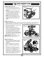
CHANGING THE BELT (FIG. 40)
●
Unplug your saw.
1. Loosen the three bolts (1) and remove the
belt cover (2).
2. Loosen the set screw (3) with a 4 mm hex
key and six hex screw (4) with a 5 mm hex
key counter-clockwise to move the motor
forward.
3. Remove and replace the belt.
4. Lift the motor housing up and retighten the
set screw (3).
5. Retighten the hex screws (4) clockwise. Do
not overtighten.
6. Replace the belt cover and tighten all bolts.
Fig. 40
1
4
3
2
4
Содержание Maximum Hawkeye Laser 055-6746-0
Страница 1: ...1 Dual beveling Compound Mitre Saw 055 6746 0 Owner s Manual Toll Free Helpline 1 800 689 9928 MD R ...
Страница 45: ...45 XIII Replacement parts MASTERCRAFT MAXIMUM COMPOUND MITRE SAW WITH LASER LINE MANUAL INSTRUCTION ...
Страница 46: ...46 Notes ...
Страница 47: ...47 Notes ...
Страница 48: ...48 Notes Imported by Mastercraft Canada Toronto Canada M4S 2B8 ...


