7
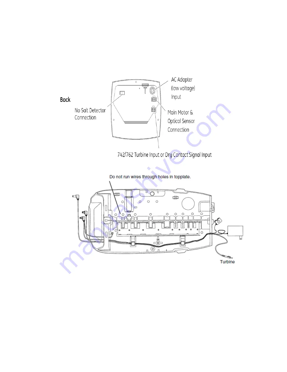
Logix Control Valve Electrical Connection:
Note: Do not touch the wiring harness between the Logix
timer and the motor, it’s positioning is critical and therefore
already installed at the factory.
1. Remove plastic control valve cover by spreading sides while
lifting.
2. Plug transformer into back of timer following existing wires.
3. Plug transformer into a properly grounded 120V/60 HZ electrical
outlet.
4. The screen will now change between the “Gallons Remaining to
Regeneration” and the current “Gallons per Minute” (gpm) flow
rate.


