


19
•
CV 60 = 0 : Stop / Drive (Standard)
•
CV 60 = 1 : Stop / Slow Drive
•
CV 60 = 2 : Slow Drive / Stop
Therefore you can also use the
slow drive with this option.
CV 50 - Bit 0 (Value 1) inverts
the switch direction “Stop /
Drive”. This may be required as
some older DCC systems as the
state of the switch direction was
not defined in the earlier DCC
standard. The Signal state is saved
in the ITC/IR Signal Decoder. So
even after a short circuit and/or
power loss (Emergency Stop) the
Signal state remains.
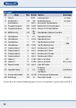
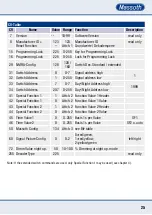
5.4 Binary CVs
There are several CV values (e.g.
29, 50) that consist of up to
eight combined single functions.
Each function has a value that is
being added up if the function is
activated. Deactivated functions
have a value of 0. The total is
set on the CV. Example – CV 50
configuration: Bit 1 – value 2:
Dimming function activated, Bit
6 – value 64: Automatic switch
activated. All other functions
deactivated:
2 + 64 = 66
•
CV60 = 0 : Halt / Fahrt (Standard)
•
CV60 = 1 : Halt / Langsamfahrt.
•
CV60 = 2 : Langsamfahrt / Halt.
Somit kann auch hier die Lang-
samfahrt genutzt werden.
Mit CV 50 - Bit 0 (Wert1) kann
die Schaltrichtung „Halt / Fahrt“
invertiert werden. Dies ist mögli-
cherweise bei älteren Digitalzent-
ralen erforderlich, da in früheren
DCC-Normen die Schaltrichtung
nicht eindeutig definiert war. Der
letzte Signalzustand wird im PZB/
IR-Signaldecoder gespeichert.
Somit bleiben nach einer Span-
nungsunterbrechung (Notaus)
die Signalzustände erhalten.
5.4 Binäre CVs
Einige CV Werte (z.B. 29, 50)
setzen sich aus bis zu acht Einzel-
funktionen zusammen. Jede Funk-
tion hat eine Wertigkeit, welche
aufaddiert wird, wenn die Funktion
aktiv ist. Inaktive Funktionen haben
den Wert 0. Die Summe wird in die
CV programmiert. Beispiel CV50
Konfiguration: Bit 1 - Wert 2: Auf
und Abblenden aktiv, Bit 6 – Wert
64: Automatik schaltbar aktiv. Alle
anderen Funktionen inaktiv:
2 + 64 = 66