MASE
1 5
FM
GB
4) INSTALLATION ANDPRELIMINARY CHECKS
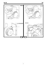
4.1) Positioning the unit
Position the power unit horizontally and make sure that
the gas exhaust is not turned towards any obstacle or
that this is at least 2 m. away from the unit. Make the
earth connection by means of the appropriate terminal
and a wire having a section of not less than 6 sq.mm
(Fig. 3).
4.2) Preliminary checks
Before start up and particulariy after every maintenance
operations it is a good rule to:
— Check the fuel and oil levels.
— Make sure that the fuel and the oil filler caps are well
secured.
— Make sure that the unit is at an equilibrium on its points
of support.
— Make sure that there are no electrical appliances
connected.
4.3) Fuel
Unscrew the fuel filler cap and fill the
tank prefarably with regular petrol NOR
84-86.
5) USE OF THE UNIT
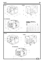
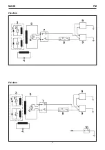
5.1) start up
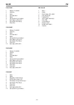
Open the fuel tap (Fig. 4 Ref. 1), and pull the starting
device lever (Fig. 4 Ref. 2); position the switch on-off
(Fig.4 Ref. 3) in position “on”; grab the handle (Fig. 4 Ref.
4) and pull softly until you feel the highest tensile strength
(this indicates that the motor is In compression). Then,
give it a decisive tug. Once the power unit is started up,
bring the starting device lever to the original position.
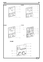
The availability of tension at the sockets is signalled by
the lighting of the green pilot-lamp (Fig. 2 Ref. 4) on the
FM 8000 the presence of tension is signalled by the
running of the hoursmeter (Fig. 2 Ref. 10).
In order to have voltage at the sockets, it is necessary to
position the commutator (Fig. 2 Ref. 3) in Pos. Nr. 1.
5.2) Use of the unit
Before connecting any appliances, let the motor run idie
for a few tens of seconds. Each unit is equipped with
two sockets: —both of the single-phase for the models
2500-4000-5600-8000 (Fig. 2 Ref. 2).
— One single-phase and one three-phase for the model
6000 (Fig. 2 Ref. 2-11). The voltages available at the
sockets are indicated in the specifications as well as on
the instrument panel of each unit.
5.3) Safety devices
The unit is equipped with a number of safety and warning
devices which protect it from abnormal operation and
improper use; These include:
— A. C. ClRCUIT SAFETY DEVICE:
the thermal circuit breaker (Fig. 2 Ref. 1-13) intervenes
in case of overloading or shortcircuiting. The coming into
operation of the circuit breaker is signalled by the turning
off of the green pilot-light (Fig. 2 Ret. 4) as well as by not
running of the hoursmeter (Fig. 2 Ref. 10) on FM 8000
and by the intervention of the thermic (Fig. 2 Ref. 1-12-
13). To reset the circuit breaker after having found and
eliminated the source of trouble wait for about a minute,
and bring the
thermic back tooriginal position.
— D.C. OUTPUT PROTECTION
DEVICE (only FM 800). Fuse 10 A (Fig. 2 Ref. 9).
— OIL WARNING DEVICE: This
device stops the unit while in operation or prevents it from
starting, if the oil level is below minimum. The oil warning
device will cause the red lamp (Fig. 5 Ref. 1) to flash. On
FM 8000 model there is no lamp.
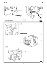
5.4) Turning off the unit
Before turning off, disconnect any connected appliances,
turn off the fuel tap7 let the motor run idle for a few tens
of seconds, turn the switch (Fig. 2 Ref. 5) and release
when the unit has actually stopped.
N.B. For FM 2500-8000 the stop device is on the engine
(Fig. 6 Ref. 1).
6) MAINTENANCE
All maintenance work shall be carried out power-off
by authorized personnel only after having let it cool
down sufficiently. We recommend strictly keeping
to the instructionss contained in the motor
manufacturer7s manual supplied along with each
unit.
If you expect the unit to remain unused for long periods,
we recommend the following:
— Replace engine oil.
— Take out the spark-plugs pour a few drops of lubricant
oil into the cylinder, let the engine complete some
revolutions so as to spread about the oil, then put the
spark-plug back in place.
—Clean the air filter elements.
—Empty the carburettor.
DANGER
Содержание 2500 M
Страница 2: ...FM MASE 2 1...
Страница 3: ...MASE 3 FM 2...
Страница 4: ...FM MASE 4 3 4...
Страница 5: ...MASE 5 FM FM2500 5 FM 8000 6...
Страница 6: ...FM MASE 6 FM 4000 FM 2500...
Страница 7: ...MASE 7 FM FM 5600 1 1 7 6 1 3 5 4 9 10 11 8 12 ECC A V R 1 3 1 2 3 5 6 7 8 9 10 4 FM 6000...
Страница 8: ...FM MASE 8 FM 8000...


