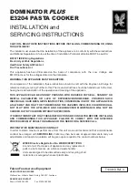
background image

8

PRODUCT DIMENSIONS

MLCR215-SS01A

Not Including Handle

34 1/16”

(865mm)

14 7/8”

(378mm)

3 3/8”

(85mm)

*Add 3/4” to depth for water line clearance

Includes 3/4”(20mm) 

Overlay Panel

22 5/16”

(567mm)*

34 1/16”

(865mm)

14 7/8”

(378mm)

3 3/8” 

(85mm)

*Add 3/4” to depth for water line clearance

MLCR215-IS01A

17” 

(432mm)

24 3/4”

(629mm)

13 15/16” 

(354mm)

8 15/16” 

(227mm)

*Add 1/2” to depth for water line clearance

MACR214-BS01A & MACR214-SS01A

22 5/16”

(567mm)*

Содержание MACR214-BS01A

Страница 1: ...UNDERCOUNTER REFRIGERATION T H E O R I G I N A L R E F R I G E R AT I O N E X P E RT S S I N C E 1 8 9 2 M LC R 2 1 5 S S 0 1 A M LC R 2 1 5 I S 0 1 A M O C R 2 1 5 S S 0 1 A M AC R 2 1 4 B S 0 1 A M...

Страница 2: ...this appliance Recognize Safety Symbols Words and Labels CAUTION Hazards or unsafe practices which could re sult in personal injury or property product damage NOTE Important information to help assure...

Страница 3: ...ill be needed as proof of damage in transit Afterwards please dispose of all items responsibly Note to Customer This merchandise was carefully packed and thoroughly inspected before leaving our plant...

Страница 4: ...ted and the grille openings kept clean Marvel does not recommend the use of a custom made grille as air flow may be restricted INSTALLING YOUR APPLIANCE Figure 2 Front Leveling Legs Front grille screw...

Страница 5: ...han opening s rear height Shorten the unit height in the front by adjusting the front legs This allows the unit to be gently tipped into the opening Readjust the front legs to level the unit after it...

Страница 6: ...nce to shut down GFCI s are generally not used on circuits with power equip ment that must run unattended for long periods of time un less required to meet local building codes and ordinances Electric...

Страница 7: ...r the front grille must NOT be obstructed and clearance is required for an electrical connection in the rear Unit can NOT be installed behind a closed cabinet door If you would like to align the face...

Страница 8: ...depth for water line clearance Includes 3 4 20mm Overlay Panel 22 5 16 567mm 34 1 16 865mm 14 7 8 378mm 3 3 8 85mm Add 3 4 to depth for water line clearance MLCR215 IS01A 17 432mm 24 3 4 629mm 13 15 1...

Страница 9: ...Handle 22 5 16 567mm Add 3 4 to depth for water line clearance 34 1 16 865mm 14 7 8 378mm 3 3 8 85mm MOCR215 SS01A Not Including Handle Add 3 4 to depth for water line clearance 22 5 16 567mm 32 813mm...

Страница 10: ...es Plastic may crack or rupture with age and cause damage to your home Do not use tape or joint compound when attaching a braided flexible water supply line that includes a rubber gasket The gasket pr...

Страница 11: ...ents other than the solenoid valve Normal operation creates some vibration A water supply line contacting an internal component or cabinet wall can cause excessive noise during operation or damage to...

Страница 12: ...de of the door To align and adjust the door 1 Gently pry off hinge cover from top of unit 2 Loosen do not remove top and bottom hinge screws using a Torx T 25 screwdriver 3 Align door squarely with ca...

Страница 13: ...inge over and install the pivot screw in the same hole from the opposite surface Figure 19 Figure 20 Figure 21 5 Remove door by tilting forward and lifting door off bottom hinge Retain shoulder washer...

Страница 14: ...Reversing the Door MACR214 Location of the unit may make it desirable to mount the door on the opposite side of the cabinet The hinge hardware will be removed and reinstalled on the opposite side of...

Страница 15: ...h hinge to top of cabinet long straight edge of hinge should align to the outside edge of cabinet Do not tighten screws 10 Rotate the door 1800 and set onto bottom hinge lift top hinge enough to allow...

Страница 16: ...ws removed in step 2 using a T 25 Torx driver Tighten screws fully 4 Gently push unit into position Be careful not to entangle the electrical cord or water line if applicable 5 Check to be sure the un...

Страница 17: ...he door frame as a guide Figure 37 It is important to ensure that all drilled holes are drilled to the correct depth in order to avoid splits in the wood when hardwood is installed 8 Locate 6 of the 6...

Страница 18: ...ce storage NOTE Figure 39 NOTE Figure 40 NOTE Certain sounds are normal during the unit s operation You may hear the compressor or fan motor the water valve or ice dropping into the ice bucket CAUTION...

Страница 19: ...mage 3 Turn the adjusting screw toward the minus sign clockwise for smaller cubes or toward the plus sign counterclockwise for larger cubes 4 Install the ice maker assembly cover Figure 41 CAUTION Adj...

Страница 20: ...ss surfaces Clean any glass surfaces with a non chlorine glass cleaner Do not use cleaners not specifically intended for stainless steel on stainless surfaces this includes glass tile and counter clea...

Страница 21: ...nit on top of the towel or other absorbent material 6 Prop the door in an open position 2 in 50 mm minimum 7 After about 1 hour remove the ice bin and discard water 8 Allow the frost to melt naturally...

Страница 22: ...n provide recommendations of service centers in your area A listing of authorized service centers is also available at www marvelrefrigeration com under the service and support section In all correspo...

Страница 23: ...igence accident or improper use maintenance instal lation service repair acts of God fire flood or other natural disasters The product must be installed operated and maintained in accordance with the...

Страница 24: ...ange without notice Such revisions do not entitle the buyer to corresponding changes improvements additions replacements or compensation for previously purchased products www marvelrefrigeration com 1...

Отзывы: