
30
Warning
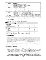
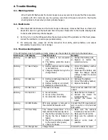
10: IP Fuse Open
Input fuse on the power stage
board is burnt.
Check and replace the input
fuse.
Warning
33: Overload 3Times Locked in bypass after overload 3
times in 30 minutes.
Remove excess loads from UPS
output first, then shut down the
UPS and restart it.
Warning
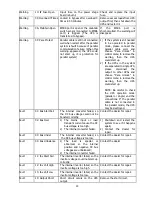
3A: Maintain Open EMBS port is open or the maintain
switch sensor (connected to EMBS
port) is trigged. (The UPS is
transferred to bypass).
If
the
EMBS
port
is
short-circuited, the warning will
disappear.
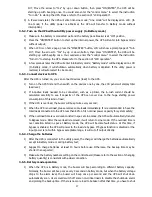
Warning
3F: Para Protect
Parallel cable is still not connected
well when restart after the parallel
system is fault because of parallel
communication failure. (When this
warning appeared, the UPS could
not start up, it is protection for
parallel system)
1)
If the system is still needed
to be operated in parallel
mode, please connect the
parallel cable well, and
choose “Para Unlock” in
control menu to remove the
warning, then the UPS
could start up.
2)
If the UPSs in the system
are separated to single UPS,
please
disconnect
the
output to other UPSs and
choose “Para Unlock” in
control menu to remove the
warning, then the UPS
could start up.
NOTE: Be careful to check
the UPS operation mode
(parallel or single) and the
connections. If the parallel
cable is not connected in
the parallel mode, the UPS
may be destroyed.
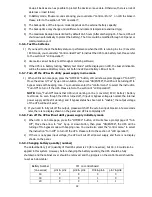
Fault
01: Bus Start Fail The internal converter failed, so
the DC bus voltage could not be
boosted correctly.
Contact the dealer for repair
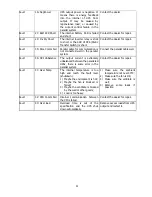
Fault
02: Bus Over
1)
The mains input or load
transient current cause the DC
bus voltage is too high;
2)
The internal converter failed.
1)
Shutdown and restart the
system to see if it happens
again;
2)
Contact the dealer for
repair.
Fault
03: Bus Under
The internal converter failed, so
the DC bus voltage is too low.
Contact the dealer for repair.
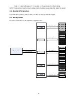
Fault
04: Bus Unbalance
1)
The load is special or
abnormal, so the internal
positive and negative DC bus
voltages are unbalanced;
2)
The internal converter failed.
Contact the dealer.
Fault
11: Inv Start Fail
The internal inverter failed, so the
inverter voltage could not start up
correctly.
Contact the dealer for repair.
Fault
12: Inv Volt High
The internal inverter failed, so the
inverter voltage is too high.
Contact the dealer for repair.
Fault
13: Inv Volt Low
The internal inverter failed, so the
inverter voltage is too low.
Contact the dealer for repair.
Fault
14: Output Short
Short circuit occurs on the UPS
output.
Remove the short circuit.


