


26
■
IMD Protocol
Use the IMD Protocol menu option to choose the protocol with which the V-R241-IMD-3G receives remote commands. Currently,
four protocols are available. Contact Marshall Electronics for the latest protocol compatibility.
Image Video
Use the Image Video protocol setting when controlling the IMD from an Image Video tally controller (e.g. TSI-1000) or other
controlling device which utilizes the Image Video protocol. The IMD #, IMD Name(S/N), and Baud Rate parameters must be set
for each screen in conjunction with the controlling device.
TSL v4.0
Use the TSL v4.0 protocol setting when controlling the IMD from a TSL tally controller, or other controlling device which utilizes
the TSL v4.0 protocol. The IMD # must be set for each screen in conjunction with the controlling device.
MEI
Use the MEI protocol setting when controlling the V-R241-IMD-3G using the Marshall Network Controller box. This protocol
allows remote control of all features on the V-R241-IMD-3G, including marker setup, video configuration, system configuration,
and image adjustments (brightness, contrast, etc.). The IMD #, IMD Group #, and Baud Rate parameters must be set in
conjunction with the Network Controller Box.
MEI-Image Video
This protocol setting accepts Image Video commands via MEI protocol, for use when an Image Video controller is connected to
the Marshall Network Controller box.
■
IMD ID #
The IMD ID # identifies each screen to the controlling device. When using the TSL protocol, the ID # of each screen should be
manually set in conjunction with the controlling device. When using the Image Video protocol, the ID # may be set automatically
by the controlling device, after each IMD is initially identified by IMD Name (see “IMD Name[S/N]” below). Available ID #s are
000-255. When using the Marshall protocol, available ID #s are 001-254.
■
IMD Group #
Each screen can be assigned an IMD Group # when using the Marshall protocol. Available Group #s are 01-254.
■
IMD Name (S/N)
Use this setting to assign a name to each screen when using the Image Video or Marshall-IV protocols. The IMD name is
equivalent to the Image Video serial number and is used by the Image Video controlling device to identify each screen. The
default IMD Name(S/N) is “M00000.” It is recommended to maintain this naming scheme in order to avoid serial number
conflicts with other Image Video devices on the same serial bus. Each name can be up to 16 ASCII characters.
Press ENTER to edit the IMD Name. Use the
and
buttons to move the cursor. Press ENTER with the cursor on the character to
be changed and use the
and
buttons to scroll through character options. Press ENTER to choose a character.
■
IMD Baud Rate
Use this setting to choose the baud rate. The baud rate must be set in conjunction with the controlling device. Available baud
rates are 300, 600, 1200, 2400, 4800, 9600, 19200, 38400, 57600, 115200. The TSL v4.0 protocol is fixed at 38400 bauds.
■
IMD Fixed Align
Use this setting to choose the horizontal alignment of the IMD text. IMD text can be justified on the left, center or right of the
screen. This setting is overridden when using IMD text via the Image Video protocol (alignment is set via Image Video protocol).
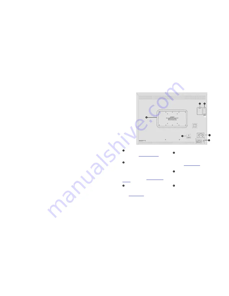
7
Rear Panel Features
3G-SDI Input and Output
The V-R241-IMD-3G has one HD-SDI input and one active loop-
through output. See
Compatible Input Formats
for details on
accepted formats.
RS-422/485 Serial Interface
The RS-422/485 ports are used to remotely control the IMD or
all V-R241-IMD-3G features, using a variety of industry
standard protocols. (Note: Connector/pin-out may need to be
adapted depending on protocol and controlling device used).
Only one connection to either port is needed to control the
monitor. The second port can be used to loop multiple
monitors in the same bus. See
IMD CONFIGURATION
SUBMENU
for further details.
Line Out Jack
The Line Out 1/8” jack on the back of the monitor takes two
channels of embedded SDI audio and provides a Line Level
audio signal. Volume CANNOT be adjusted for this output.
See the
Audio Configuration
section for instructions on how to
select the two audio channels.
Tally / GPI Interface (HD-15)
LED tally, OSD tally and GPI can be activated via the HD-15
connector by connecting the corresponding pin to ground. A
variety of external devices can be used to perform the contact
closure. No additional power should be supplied to the HD-15
port. See the
System Configuration
section for details on
configuring GPI.
Power Input
Connect the 24VDC input to the power input connector.
Power can be supplied from the included power supply, or
from a variety of DC sources supplying at least 6.25 Amps at
24 Volts.
VESA 75 mm / 100 mm Hole Patterns
VESA standard 75 mm and 100 mm hole patterns are provided
to accommodate a variety of custom mounting options.
Содержание V-R241-IMD-3G
Страница 2: ...2 This page intentionally left blank 31...


