6
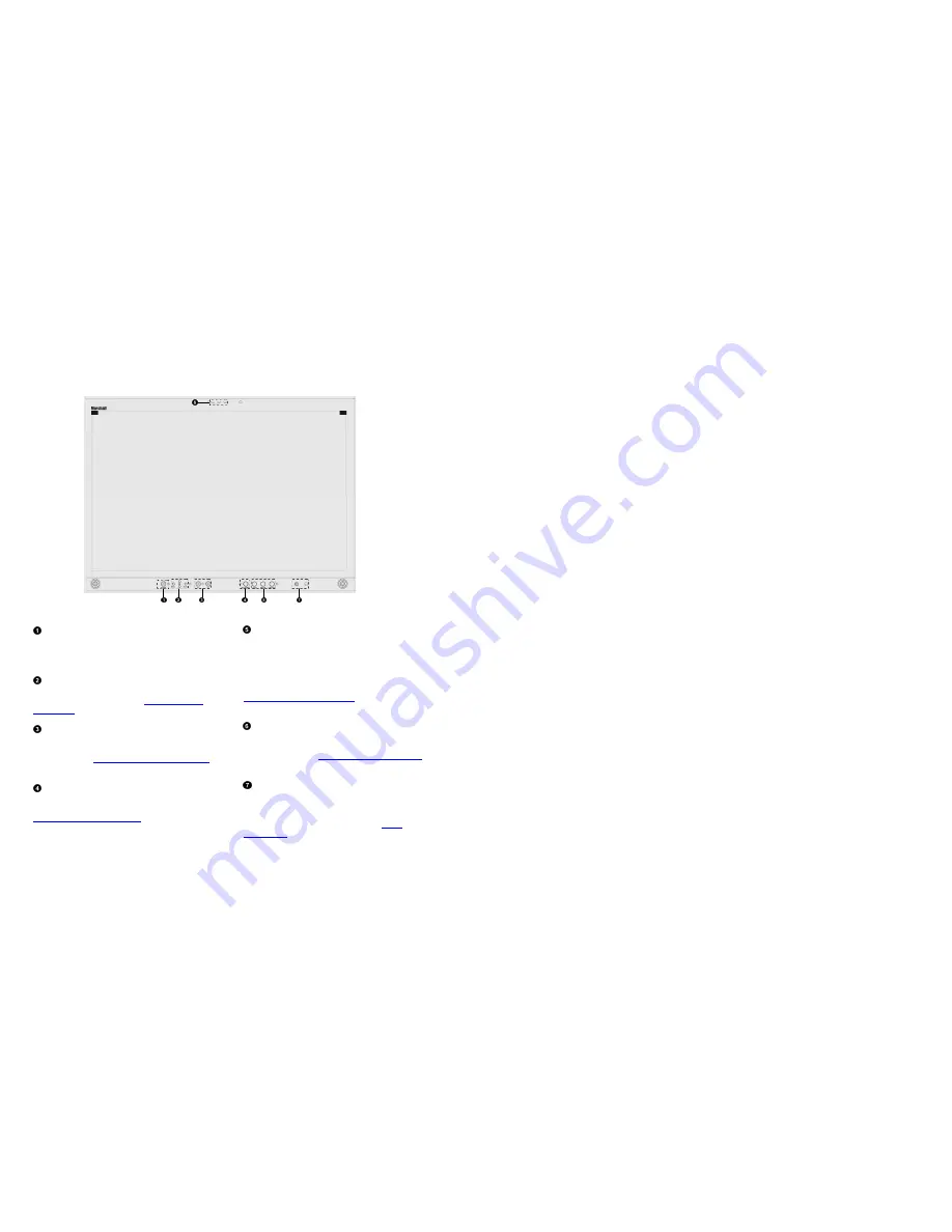
Top and Front Panel Features
Power Button
Turn the monitor panel off or on by pressing the power
button. In the ON state, the LED on the power button will
illuminate green.
Menu Navigation Buttons
Use the Menu, ↑, ↓, and Select buttons to display and
navigate the on-screen menu. See
MAIN MENU AND
NAVIGATION
for details on using the Menu.
User-Definable Function Buttons
Two user-definable function buttons can be used for direct
access to various settings. Functions are assigned using the on-
screen menu. See
SYSTEM CONFIGURATION SUBMENU
for
information on changing Functions.
RotoMenu
™
Knob
The RotoMenu
™
knob is alternate means of accessing and
navigating the main menu, using only a single control. See the
Using the RotoMenu knob section
for details on using the
RotoMenu. Also, turning the RotoMenu
™
knob before
pressing it adjusts the Headphone volume on monitors with an
available Headphone Jack.
Image Adjustment Knobs
Use the image adjustment knobs to adjust color saturation,
brightness and contrast of the image. The status of each image
adjustment parameter is shown on the bottom left of the
screen, with values ranging from 0 to 100. Pressing a knob
once displays the current value. Pressing a knob twice resets
the corresponding adjustment to the default setting. See
VIDEO CONFIGURATION SUBMENU
for information on Blue
Only calibration.
LED Tally
Two LED tally lights (red, green) are available near each
individual screen. Each tally light can be controlled from a
variety of sources. See
IMD CONFIGURATION SUBMENU
for
more details.
Headphone Jack
The 1/8” jack on the front of the monitor takes two channels
of embedded SDI audio and provides a Headphone audio
signal. Volume can be adjusted via the RotoMenu knob or in
the Audio Configuration submenu. See the
Audio
Configuration
section for instructions on how to select the two
audio channels.
27
■
IMD Fixed Color
Use this setting to choose the color of the IMD Fixed String text (see below). Available colors are red, green, and yellow. This
setting does not affect text color when using IMD text via the Image Video or TSL v4.0 protocols (text color is set via the
protocols).
■
IMD Fixed String
Use this setting to display static IMD text on the screen. This setting is used to enter IMD text locally, when a serial protocol is not
used for remote control. The IMD Fixed String is saved after power cycle. The IMD Fixed String will be overridden by serial
protocol commands.
Press ENTER to edit the IMD Fixed String. Use the
and
buttons to move the cursor. Press ENTER with the cursor on the
character to be changed and use the
and
buttons to scroll through character options. Press ENTER to choose a character.
■
Tally Source
The V-R241-IMD-3G tally (OSD and LED) can be controlled in a variety of different ways. Use the Tally Source setting to choose
how tally is controlled:
Standard
Use the Standard setting to control tally via contact closure on the HD-15 tally interface.
Image Video HW
Use the Image Video HW setting to control Image Video tally states via contact closure on the HD-15 tally interface. Contact
closure of the Red pin corresponds to Image Video Tally 1, and the Green pin maps to Image Video Tally 2. Contact closure
(ground) corresponds to a LOW state, and open circuit corresponds to a HIGH state. This mode requires the IMD Tally Mode
parameter to be set. Consult Image Video documentation for further information.
Image Video 422
Use the Image Video 422 setting to control Image Video tally states via the Image Video serial protocol. LED and OSD tally will be
disabled in this mode, as Image Video tally states are manifested in the text color and other parameters. This mode requires the
IMD Tally Mode parameter to be set. Consult Image Video documentation for further information.
St IV422
Use the Image Video 422 setting to control Image Video tally states via the Image Video serial protocol, while controlling LED and
OSD tally using contact closure on the HD-15 tally interface. This mode requires the IMD Tally Mode parameter to be set. Consult
Image Video documentation for further information.
TSL/MEI 422
Use the TSL/MEI 422 setting to control OSD and LED tally via the TSL or Marshall serial protocols.
■
IMD Tally Mode
Use this setting when using Image Video tally control. Choose one of the following settings, in conjunction with the Image Video
controlling device. T1, T2, T1T2, T2T1, T1-, T2-, T1T2-, T2T1-. Consult Image Video documentation for further information.
Содержание V-R241-IMD-3G
Страница 2: ...2 This page intentionally left blank 31...