background image


26 


On-Screen Menu (continued)
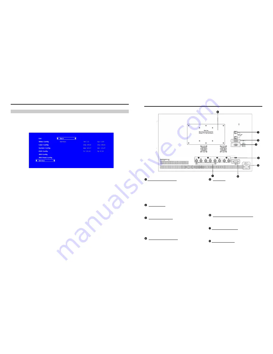


SERVICE SUBMENU 


  Software Version Display 


The Main Board, Keypad, and FPGA software version numbers are displayed. 


.  


The following information is displayed: 


• rel: 


Release Package version number 


• kp 


Keypad version number 


• ima 


A/B Input module version 


• imc 


C/D Input module version 


• ipa 


Input processor firmware 


• ipc 


Input processor firmware 


• fc 


Combiner FPGA version 


• fp 


Packet decoder FPGA  version 

Service Menu 


Rear Panel Features


RS-422/485 Serial Interface  

The RS-422/485 ports are used to remotely control the 
IMD or all QV261-HDSDI features, using a variety of 
industry standard protocols. (Note: Connector/pin-out 
may need to be adapted depending on protocol and 
controlling device used. See pin-out details on page 
27.)
 Only one connection to either port is needed to 
control the monitor. The second port can be used to loop 
multiple monitors in the same bus. 


PG-1 Connector 
DO NOT USE! This is for factory use only. 
Connecting any device to this port  may damage the 
unit.  


Tally Interface (HD-15)  
The OSD tally can be activated via the HD-15 
connector by connecting the corresponding pin to 
ground. A variety of external devices can be used to 
perform the contact closure. No additional power 
should be supplied to the HD-15 port. See pin-out 
details on page 28. 


HD-SDI Inputs and Outputs  
The QV261-HDSDI has four HD-SDI inputs  
and four active loop-through outputs. 


Power Input 
Connect the 24VDC input to the XLR power input 
connector. Power can be supplied from the  
included power supply, or from a variety of DC 
sources supplying at least 6.0 Amps at 24 Volts. 
IMPORTANT: If using a power source other than  
the included power supply, be sure that the  
polarity of the DC input is correct: 


Pin 1:  GND 


Pin 2:  N/C 


Pin 3:  N/C 


Pin 4:  +24VDC 


VESA 75mm and 200 mm Hole Pattern 
VESA-standard 75 mm and 200 mm hole- 
patterns are provided to accommodate a  
variety of custom mounting options. 


Desktop Mounting Holes 

These holes are used when attaching the monitor to 
the optional desktop stand.  
See page 5 for details. 


DVI-I Input Connector 

Integrated DVI Digital and Analog VGA input. 
Includes EDID and HDCP for connection to 
Computers, DVD Players, Rasterizers, etc.   

Содержание QV261-HDSDI

Страница 1: ...1910 East Maple Ave El Segundo CA 90245 Tel 800 800 6608 310 333 0606 Fax 310 333 0688 www LCDRacks com sales lcdracks com 2010 0318 Marshall Electronics QV261 HDSDI 26 Full Resolution Quad Viewer Mon...

Страница 2: ...2 This page intentionally left blank 31 This page intentionally left blank...

Страница 3: ...VIGATION 12 Making Changes to an Individual Channel 12 Group Link Changes 13 VIDEO CONFIGURATION SUBMENU 14 Monochrome Mode 14 Blue Only Mode 15 Pixel to Pixel Mode 15 Aspect Ratio Settings 15 Curtain...

Страница 4: ...ide mode Ability to view 4 inputs on the screen at once Each input source is scaled and positioned in real time so that all 4 can be seen DVI I input can replace HD SDI input 4 in this mode There are...

Страница 5: ...of pixels not to exceed three to fail on the periphery of the display active viewing area Marshall Electronics reserves the option to refuse service for display pixel failure if deemed unobtrusive to...

Страница 6: ...Pixels 1920 x RGB x 1200 Color Depth 8 bit Viewing Angle h x v 178 x 178 Brightness 500 cd m 2 Contrast Ratio 800 1 Pixel Pitch h x v 0 2865x 0 2865mm Burn In Warning The QV261 HDSDI uses a high qual...

Страница 7: ...e the unit Tally Interface HD 15 The OSD tally can be activated via the HD 15 connector by connecting the corresponding pin to ground A variety of external devices can be used to perform the contact c...

Страница 8: ...Video or TSL v4 0 protocols text color is set via the protocols IMD Fixed Align Use this setting to choose the horizontal alignment of the IMD text IMD text can be justified on the left center or rig...

Страница 9: ...u knob to edit the IMD Name Rotate the RotoMenu knob to move the cursor Press the RotoMenu knob with the cursor on the character to be changed then rotate the knob to scroll through the character set...

Страница 10: ...mage Video commands via MEI protocol for use when an Image Video controller is connected to the Marshall Network Controller box Tally Source The QV261 HDSDI OSD tally can be controlled in a variety of...

Страница 11: ...Config Analog Phase 0 31 DVI Analog input only Back Return to Main Menu Red Offset Per Channel 0 100 Green Offset Per Channel 0 100 Color Config Blue Offset Per Channel 0 100 Red Gain Per Channel 0 1...

Страница 12: ...ual channel select the particular submenu you would like to modify in this case the Monochrome option by turning your RotoMenu left or right from the screen above Main Menu 21 Audio Monitor Use the Au...

Страница 13: ...ellow RGY mode single color activated RGY mode two colors activated RGY mode three colors activated red gree n red gree n 13 Your current position in the menu is indicated by the green highlight When...

Страница 14: ...le picture Video Configuration Submenu 19 Status Display Use this setting to enable or disable status display When enabled the current video input standard is displayed on the top left of the screen W...

Страница 15: ...blue appear to match in brightness Pixel to Pixel Mode Use this setting to enable Pixel to Pixel mode This mode bypasses the monitor s internal scaling function and displays images in their native res...

Страница 16: ...alog to digital conversion 0 31 value 17 COLOR CONFIGURATION SUBMENU Use the Color Configuration submenu to adjust the Red Green and Blue Offset and Gain values of all four HD SDI channels the DVI D i...

Отзывы: