Gas Conversion Instructions
Kit Number
Description Pilot
Orifice Burner Orifice
Brass (1000-255)
Air Shutter
Hi/Lo Regulator
3927-CKLP
4634-CKLP
LP Conversion
-Millivolt-
1001-P167SI
#30
(977.167)
#46
#42
Full Open
Full Open
1001-P202SI
(0.907.202)
3927-CKNG
4634-CKNG
NG Conversion
-Millivolt-
1001-P165SI
#51
(977.165)
#29
#25
1/4”
3/8”
1001-P201SI
(0.907.201)
3927-CKLPi
4634-CKLPi
LP Conversion
-IPI-
1001-P168SI
#35
(977.168)
#46
#42
Full Open
Full Open
1002-P014SI
(0.907.014)
3927-CKNGi
4634-CKNGi
NG Conversion
-IPI-
1001-P166SI
#62
(977.166)
#29
#25
1/4”
3/8”
1002-P016SI
(0.907.016)
Refer to “
Gas Specifications Chart
” for inlet pressures and input ratings. Clock meter to verify input rate. Place conversion label as
close to converted gas control as possible. Refer to lighting instructions to verify the normal operating sequence of the ignition system.
There are three main components involved in converting this appliance for use with an alternate fuel source. They are the
valve, main burner system, and pilot burner system. Improper modification of any of these components may degrade the
appliance’s performance and can lead to unsafe operation. Ensure that these adjustments are done properly.
Converting this appliance can only be done with a prescribed kit. These kits cannot be modified in any way and must be
installed in accordance to the instructions supplied. The instruction manual supplied with the kit supersedes this section of the
installation manual. For more information with regards to the kit involved consult the Parts List MQZDV3927 on
page 50.
IMPORTANT: Always check for gas leaks with a soap and water solution. DO NOT USE OPEN FLAME FOR LEAK TESTING.
Main Burner Conversion
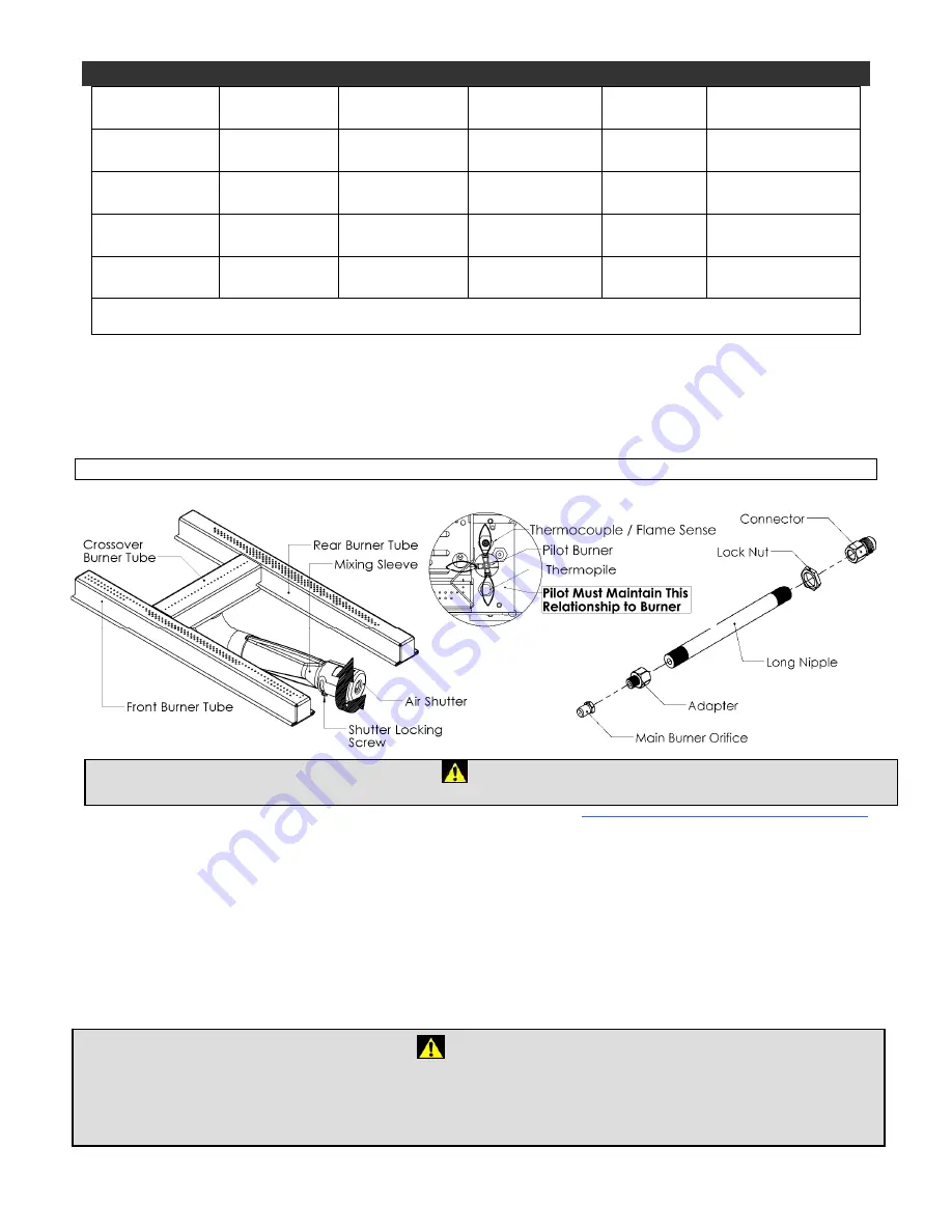
1. Remove the burner tube from the burner system (refer to page 24).
2. To adjust the Primary Air Setting, loosen the Air Shutter Adjustment Screw and rotate the Air Shutter to the appropriate
gap position of the new fuel. A drill bit of the proper diameter or a measuring device such as a caliper maybe used to
establish the gap opening.
3. Replace the old orifice with one for the new fuel. Pipe sealing compound is required to ensure a proper seal between the
orifice and the adapter fitting.
4. For information with regards to the size of the Primary Air Setting and orifice, please refer to page 32. To reinstall the
burner tube assembly please refer to page 24 & 24.
Valve Conversion
The HI/LO diaphragm of the gas valve must be replaced to accommodate the alternate fuel source. Please follow the
instructions that accompany the conversion kit for the gas valve.
Figure 19 - Main burner fuel conversion guide.
Caution
:
The gas supply shall be shut off prior to disconnecting the electrical power, before proceeding with the conversion.
WARNING
This conversion kit shall be installed by a qualified service agency in accordance with the manufacturer's instructions and all
applicable codes and requirements of the authority having jurisdiction. If the information in these instructions is not followed
exactly a fire, explosion or production of carbon monoxide may result causing property damage, personal injury or loss of life.
The qualified service agency is responsible for the proper installation of this kit. The installation is not proper and complete until
the operation of the converted appliance is checked as specified in the manufacturer's instructions supplied with kit.
35


