background image

Rutland 504 Windcharger                                                                                                                                           Installation & Operation

Doc No: SM-150 Issue C 17.03.14                                                    26                                                                                Marlec Eng Co Ltd 

Kurzanleitung mit zwölf Anhaltspunkten

1. Wählen sie eine offene Stelle für die Montage Ihres Windchargers in einem bestimmten Luftstrom 
und unter der Vermeidung von Hindernissen. An Bord sollte der Windcharger mindestens 2.4 Meter 
über dem Deck und zu Lande mindestens 4 - 6 Meter hoch angebracht werden. 

Lesen Sie den 

vollständigen Absatz zu: An einer Stelle befestigen

 (Siting).

2. Wählen Sie einen Mast  mit einem Innendurchmesser von 31.7mm und einem Außendurchmesser 
von  nicht  größer  als  38.1  mm  und  mindestens  für  den  Oberen  0.6m,  um  (i)einen  Nebenschaden  zu 
vermeiden und (ii) die Bedingungen der Garantie zu erfüllen. 

3. Montieren sie eines der Aufladekontrollgeräte von der Firma Marlec an eine geeignete senkrechte 
Oberfläche und in der Nähe der Batterie. Befolgen Sie die Anleitung, die mit dem Aufladekontrollgerät 
mitgeliefert wurde.  

4.  Bohren  Sie,  falls  erforderlich,  in  den  Montagemast  zur  Vorbereitung  der  Befestigung  und 
Inbetriebnahme des Windchargers. 

Siehe Montage und Installation [

Assembly and Installation]

.

5.  Wählen  sie  ein  geeignetes  zweiadriges  Kabel  für  den  Anschluss  des  Windchargers  zum 
Aufladekontrollgerät.  Bis  zu  20  Meter,  dies  sollte  mindestens  von  einer  2.5mm²  Querschnittsfläche 
sein.  Ein  Kurzabschnitt  von  einer  4mm²  Querschnittsfläche  ist  für  die  Verbindung  zwischen  dem 
Aufladekontrollgerät und der Batterie erforderlich. 

Für weitere Abstände beziehen Sie sich bitte auf die 

Tabelle Kabelspezifikationen 

[Cable Specifications]. 

6. Bringen Sie den Montagemast in eine bestimmte Stellung, sodass das gewählte Kabel aufgezogen 
werden kann, das kann auch auf dem Boden durchgeführt werden, bevor sie den Mast anheben.

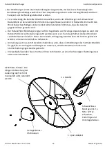
7. Das Heck- und Vorderteil an den Windcharger mit den mitgelieferten Befestigungsteilen montieren.  

8. Schließen Sie das durchgezogene Kabel am Mast mit dem Kabelausgang des Windchargers mit der 
mitgelieferten  Anschlussleiste  an  und  mit  Isolierband  umwickeln.  Es  kann  als  Alternative  eine 
einklinkende Steckvorrichtung verwendet werden. 

Wir empfehlen das Kabel zurückzuschlingen, um es 

mit einem Kabelbinder zu befestigen und eine Zugentlastung am Verbindungsstück zu erzielen.  

9.  Die  Kabel  mit  Sorgfalt  am  Mast  hinunter  schieben,  während  das  Passstück  am  Mast  herunter 
gegleitet  wird.  Die  Löcher  in eine  Reihe  bringen und an der  Stelle mit den mitgelieferten  Schrauben 
und Muttern  befestigen  und mit  dem  Sechskantstiftschlüssel  befestigen. 

Die  Turbine  darf  nicht  sich 

nicht unbehindert im Kreis drehen. 

10.  Das  Aufladekontrollgerät  neben  der  Batterie  lokalisieren  und  mit  Sorgfalt  ALLE  Richtlinien  und 
Installationsanweisungen für den Anschluss an den Windcharger bis durch zur Batterie befolgen.   

11.  Sicherstellen,  dass  die  Batterieanschlüsse  dauerhaft  sind,  da  der  Windcharger  NIE  ohne  einen 
Anschluss mit der Batterie in Betrieb genommen werden darf. 

12.  Den  Windcharger  anheben  und  befestigen.  Die  Drehbewegungen  können  nun  durchgeführt 
werden. Befolgen sie die im folgenden erläuterte “Inbetriebnahme – 4-Punkte Überprüfliste“. [

Up and 

Running- Four Points Final Checklist]

, ebenso die 

“Allgemeinen Richtlinien und Gefahrenhinweise”

,

die sich auf die obengenannten Punkte beziehen. 

Содержание Rutland 504 efurl

Страница 1: ...Rutland 504 Windcharger Rutland 504 efurl Owners Manual Installation and Operation GB DE ES FR IT Doc No SM 150 Issue C 17 03 14 ...

Страница 2: ......

Страница 3: ...al Wiring Diagram for the Rutland 504 Windcharger 10 Siting The Windcharger 11 General Considerations 11 On Board Systems Rutland 504 model 12 Land Based Systems Rutland 504 efurl model 13 Further System Requirements Batteries 14 Cable Specification 14 Specification and Performance Guideline Performance Curve 15 Maintenance and Troubleshooting Inspection and Maintenance 16 Troubleshooting 16 Instr...

Страница 4: ...d start up maximises power generation in low winds x High grade construction materials for durability U V stability and weather resistance x Provides a D C power supply to charge 12 V battery banks where low power is needed for domestic devices as well as navigation equipment etc x Rutland 504 Windcharger model Designed for use on board sailing yachts and temporary motor caravan applications x Rut...

Страница 5: ...ured to the pole with rope Avoid leaving the turbine tied up for any period of time we recommend that the turbine either be covered to give protection from the weather or removed and stored in a dry location We recommend the use of Marlec charge regulator that includes a shutdown switch x Choose a calm day to install the equipment and consider other safety aspects No attempt to repair the system s...

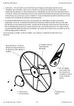
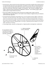
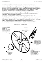
Страница 6: ... and stays x Cable x Batteries x Battery Terminals x Connector Blocks as determined by your total system Nose Cone with 3 x snap rivets Safety Turbine The blades incorporating the outer ring must not be tampered with or altered Post Adaptor Assembly This fits into a pole of 31 7mm internal diameter and NO MORE THAN 38 1mm external diameter Nacelle containing Windshaft Assembly Tail Fin Assembly wi...

Страница 7: ...nal area is required to link the regulator to the battery 6 Position the mounting pole this may be done on the ground before raising the pole so that the selected cable can be threaded along it 7 Fit the tail and nose to the Windcharger using fasteners provided 8 Join the cable threaded through the pole to the Windcharger output cable using the connector block provided Wrap with insulating tape Al...

Страница 8: ... Kit for use with Mount Kit CA 12 32 x Rutland 504 Land Tower Rigging Kit for temporary installations CA 12 12 CA 12 13 x Tube sections to adapt to own pole arrangement 1000mm CA 12 15 or 500mm CA 12 16 Fig 1 Fig 2 A Fig 2 B Post Adaptor ї 40mm ї Assembly Installation Detailed Instructions Tail Nose Assembly Fig 2 A Fig 2 B 1 Place the generator nose down on a flat soft surface 2 Fit the tail into...

Страница 9: ...ching type plug and socket 5 Locate the wind generator into the tower whilst gently easing the cable from the tower base to ensure the cable is not trapped Secure the wind generator to the tower using the button cap screws and shake proof washers provided tighten using the 6mm Allen key provided Up and Running Four Point Final Checklist Before raising and securing the wind generator 1 Check the ti...

Страница 10: ...le battery bank optional solar panel up to 160W Fig 4 HRDi Regulator for dual battery charging optional solar panel up to 160W Typical Wiring Diagrams For The Rutland 504 Windcharger CAUTION Note for solar panel connections to all regulators 1 Maximum solar panel ratings are based on 25 C downrate for use in higher ambient temperatures 2 A diode must be fitted to the solar panel s to prevent rever...

Страница 11: ... the fast moving upper air and the slow moving air close to the ground and the resulting decrease in average wind speed as one gets closer to the ground Turbulence is caused by the wind passing over obstructions such as moored boats trees and buildings Both wind sheer and turbulence diminish with height and can be overcome simply by putting the turbine sufficiently high above them It is therefore ...

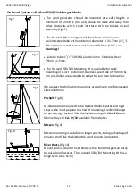
Страница 12: ...ing or short sections of stainless steel tube of 500mm 1m pre drilled are available to adapt to your own fabrication On Board Systems Rutland 504 Windcharger Model We suggest the following mountings according to preference and site conditions Pushpit Fig 8 A suitable pole mounted to the deck with deck plates and rigid stays is the most popular method of mounting the Windcharger on yachts e g Rutla...

Страница 13: ...ed water pipe adapted down to 31 7mm for a minimum length of 500mm at the top section The tube must be supported by a minimum of two sets of three guy lines The attachment points for the guy lines to the tower should be securely fixed to the tower Follow these guidelines x The guy wires should be a minimum of 3mm in diameter x The shackles should be a minimum of 5mm in diameter x Rigging screws sh...

Страница 14: ...the charge regulators available from Marlec is fitted to prevent batteries becoming overcharged in strong winds and during low energy consumption periods A regulator is essential where gel and sealed batteries are used x Batteries may be linked as shown in the Fig 13 It is essential to observe polarity as follows Red is Positive Black is Negative Batteries in parallel to increase ampere hours Fig ...

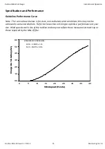
Страница 15: ...ind conditions this may not be achieved in some installations Refer to the section on Siting to optimise performance at your site Wind speeds are in situ of the turbine and may not reflect those measured at mast top or those reported by the Met Office 0 0 1 0 2 0 3 0 4 0 5 0 6 0 0 5 10 15 20 25 30 35 40 W indspeed Knots C harg ein to12vb attery A m p eres WINDSPEED CONVERSION MPH KNOTS x 1 15 M S ...

Страница 16: ...ntly during the first year 5 The unit can be wiped with a mild detergent and rinsed with water to remove dirt and debris Note The Wind charger is designed for continuous running this achieves maximum resistance to water ingress Should the unit be restrained for any extended period it is recommended that it be covered or removed to a dry location Trouble Shooting In the unlikely event that your Rut...

Страница 17: ...t the wind gen directly to the battery Set the digital multi meter to DC Amps and measure power between the wind gen and the battery If a reading is measured providing there is sufficient wind then the regulator is faulty E If the wind turbine fails to deliver any current or open circuit V reading undertake the further tests below 5 Mechanical inspection It may be necessary to remove the Wind char...

Страница 18: ...risquent de heurter le mât et de s endommager Une pale brisée provoque un déséquilibre capable d entraîner des dégâts importants x Lorsqu elle fonctionne l éolienne peu générer de l électricité à haute tension c est pourquoi elle ne doit pas tourner tant qu elle n est pas reliée à un régulateur ou à des batteries Raccorder directement l éolienne à l installation électrique peut provoquer des dégât...

Страница 19: ...une utilisation sur des bateaux à voiles ou certaines applications terrestres L éolienne Rutland 504 efurl doit être utilisée dans des zones de vents forts permanents ou des utilisations terrestres Lorsque des vents d orage sont annoncés l éolienne peut être immobilisée pour prévenir les risques d usure et de casse Notez bien que le non respect de ces recommandations fabricant entraine l invalidat...

Страница 20: ...s longueurs se reporter au chapitre Type de câble 6 Passer le câble dans le mât cela peut se faire au sol avant de dresser le mât 7 Fixer l aileron et le cône avant sur l éolienne à l aide des fixations fournies 8 Utiliser le bloc de connexion fourni pour raccorder le câble passé dans le mât au câble sur l éolienne Protéger la connexion avec du ruban isolant Vous pouvez aussi utiliser une prise No...

Страница 21: ... aunque sea en los 0 5m superiores No utilice mástiles más grandes ya que esto reducirá el espacio entre la torre y la paleta En condiciones de vientos fuertes esto puedo provocar daños al cargador eólico ya que la paleta entra en contacto con el mástil de montaje Una paleta rota producirá un desequilibrio en la turbina y daños posteriores x Al girar el cargador eólico es capaz de generar voltajes...

Страница 22: ... al cargador eólico y la instalación incorrecta anulará la garantía x El aerogenerador Rutland 504 es adecuado para su uso en los barcos de vela y algunas aplicaciones terrestres El efurl Rutland 504 se debe utilizar siempre en instalaciones permanentes o en tierra en zonas de vientos fuertes Cuando se pronostican vientos de tormenta el aerogenerador restringe su fuerza para minimizar el desgaste ...

Страница 23: ...ificaciones para cables 6 Coloque el mástil de montaje esto puede hacerlo en el piso antes de levantar el mástil de tal manera que el cable seleccionado pueda enroscarse a lo largo del mismo 7 Ajuste la cola y la nariz del cargador eólico mediante los fijadores proporcionados 8 Una el cable enroscado en el mástil al cable de salida del cargador eólico mediante el bloque conector proporcionado Envu...

Страница 24: ...chen dem Mast und dem Rotorblattspiels führt Bei hohen Windbedingungen könnte es beim Windcharger zu Schaden führen da das Rotorblatt mit dem festmontierten Mast in Kontakt kommen könnte Ein zerbrochenes Rotorblatt verursacht ein Ungleichgewicht der Turbine und dementsprechend Schäden x Bei der Drehbewegung ist der Windcharger in der Lage Stromspannungen höher als die Nennspannung zu erzeugen Es d...

Страница 25: ...ür Segelboote und für einige Anwendungen zu Land Der Rutland 504 efurl sollte dann eingesetzt werden wenn es sich um dauerhaften starken Wind oder Landinstallationen handelt Wenn Sturmwinde vorhergesagt werden kann die Turbine gedrosselt werden um einen Verschleiß zu reduzieren x Anmerkung wenn es vom Hersteller empfohlen wurde dass ein Windcharger der Furlmatic Modelle für jegliche Art von Segelv...

Страница 26: ...abelle Kabelspezifikationen Cable Specifications 6 Bringen Sie den Montagemast in eine bestimmte Stellung sodass das gewählte Kabel aufgezogen werden kann das kann auch auf dem Boden durchgeführt werden bevor sie den Mast anheben 7 Das Heck und Vorderteil an den Windcharger mit den mitgelieferten Befestigungsteilen montieren 8 Schließen Sie das durchgezogene Kabel am Mast mit dem Kabelausgang des ...

Страница 27: ...rrebbero la distanza tra la pala e la torre In condizioni di vento forte potrebbero verificarsi danni al generatore eolico poiché la pala potrebbe entrare in contatto con il palo di montaggio Una pala spezzata provocherà uno squilibrio della turbina e un conseguente danno x Mentre il generatore eolico gira è in grado di generare tensioni in eccesso rispetto alla tensione nominale La turbina non de...

Страница 28: ... eolico e l installazione non corretta invaliderà la garanzia xIl generatore eolico Rutland 504 è adatto per barche a vela e alcune applicazioni a terra Il Rutland 504 efurl dovrà essere sempre utilizzato in caso di applicazioni terrestri permanenti o in aree sogette a forti vente Quando si prevedono venti di tempesta la ventola podrà essere rallentata minimizzandone il logorio Si noti che qualora...

Страница 29: ...sizionare il palo di montaggio questo può essere eseguito sul terreno prima di sollevare il palo in modo che il cavo selezionato possa essere filettato lungo di esso 7 Montare la coda e il naso al generatore eolico mediante i dispositivi di fissaggio in dotazione 8 Unire il cavo filettato lungo il palo al cavo di uscita del generatore eolico utilizzando il connettore in dotazione Avvolgere con nas...

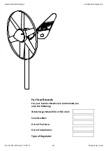
Страница 30: ...ration Doc No SM 150 Issue C 17 03 14 30 Marlec Eng Co Ltd For Your Records For your future reference we recommend you note the following Windcharger Model 504 or 504 efurl Serial Number Date of Purchase Date of Installation Type of Regulator ...

Страница 31: ...ring Company Limited Rutland House Trevithick Road Corby Northamptonshire NN17 5XY England or to an authorised Marlec agent This Warranty is void in the event of improper installation owner neglect misuse damage caused by flying debris or natural disasters including lightning and hurricane force winds This warranty does not extend to support posts inverters batteries or ancillary equipment not sup...

Страница 32: ...eering Co Ltd Rutland House Trevithick Road Corby NN17 5XY Tel 44 0 1536 201588 Fax 44 0 1536 400211 sales marlec co uk www marlec co uk Solar power that works with your Rutland Windcharger Energy saving solar panels for your home and business Solar power to keep batteries topped up on board ...

Отзывы:

Похожие инструкции для Rutland 504 efurl