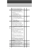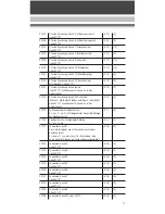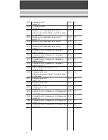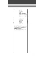
- Steam generator ..........................1
- Tank volume..........................8 cm
2
- Steam chuffs synchronized with
wheel revolutions
- DCC interface (24811) .................1
- Length.............ca. 550mm (21.7in)
- Weigth.................ca. 5,000g (11lb)
- Simulated firebox fire
- Voltage limitation system (5V)
- Operating mode selector, four-way
- The following vehicle parts can be
opened:
- cab doors
- roof hatchet
- steambox door
- tender cover
Features
(24812)
- Factory-installed onboard sound
and MTS decoder for analog and
digital operation
- Remote control of sound features
(with Multi- Train System)
- Digital steam engine sound3
- MTS features a load-dependent
steam engine sound
- Bell and whistle
- Brake sound
- Air pump, safety valve and steam
sounds
- Coal shoveling sound
- Volume control
Scope of delivery (accessories)
- Puppet, engine driver...................1
- Steaming and cleaning
fluid2......................................10ml
- Mounting plate for
magnet (incl. screws) ..................1
- Gangman's handle .......................2
- Operating instructions .................1
- Sound trigger magnet..................2
Prior to start-up
ATTENTION!
During extended opera-
tion, this model may leave carbon
dust or other debris around the track.
This dust and debris can stain car-
pets and other materials. Consider
this when setting up the track.
Note:
Ernst Paul Lehmann Patentwerk and
LGB of America are not liable for any
damages.
Check clearances!
ATTENTION!
In curves, the cab
swings out leisurely, depending on
the curve radius (Fig. 1), for this rea-
son, check out all obstacles, such as:
- bridges
- platforms
- tunnels etc.
Troubleshooting:
- Place a straight track section in
front of the obstacle.
Gangman's handle installation
Put the handles (Fig. 2) into the
openings prepared for them.
Mounting plate
Note:
The mounting plate is required if the
loco is to be fitted with an Magnet2.
Function:
The Loco Magnet is used to trigger
the Track Contact2. It is supplied
separately.
Installation:
Either at the front or rear part of the
gearbox.
- Next to the center-pivot joint under-
neath the gearbox, there are two
screws on each side (Fig. 3).
- Remove either the front or the rear
screws.
- Place the mounting bracket so that
the number faces down and cannot
be seen. The mounting bracket
must be oriented toward the end of
the gearbox and not toward the
joint.
- Use the two screws to attach the
mounting bracket to the gearbox.
- Now you can use double-sided
adhesive tape to attach the Loco
Magnet between the grooves
20

