background image


6


Manual Shut-Off Valve: 

This  installer-supplied  valve  must  be  installed  in  the  gas  service  line  ahead  of  the  appliance  and 
regulator in the gas stream and in a position accessible in the event of an emergency. 

Pressure Regulator: 

Gas pressure regulator provided with the equipment must be installed when the appliance is connected 
to gas supply. 
 
All commercial cooking equipment must have a pressure regulator on the incoming service line for safe 
and efficient operation, since service pressure may fluctuate with local demand. The pressure regulator 
comes with the oven. Failure to install the pressure regulator will void the equipment warranty! 
 
The regulators supplied with MARKET FORGE INDUSTRIES, INC. Ovens, have 3/4” inlet /outlet openings 
and  are  adjusted  at  the  factory  for  5”  WC  (Natural  gas)  or  10”  WC  (Propane  gas)  depending  on 
customer’s ordering instructions. 
 
Prior  to  connecting  the  regulator,  check  the  incoming  line  pressure,  as  these  regulators  can  only 
withstand a maximum pressure of ½ PSI (14”WC). If the line pressure is beyond this limit, a step-down 
regulator  will  be  required.  The  arrow  shown  on  the  bottom  of  the  regulator  body  shows  gas  flow 
direction; it should point downstream to the appliance. The red air vent cap on the top regulator is part 
of the regulator and should not be removed. 
  
Any  adjustments  to  regulators  must  be  made  only  by  qualified  service  personnel  with  the  proper 
equipment.  

Connections: 

Please check installer-supplied intake pipes visually and /or blow them out with compressed air to clear 
any  dirt  particles,  threading  chips,  or  other  foreign  matter  before  installing  a  service  line.  When  gas 
pressure  is  applied  these  particles  can  clog  orifices.    All  connections  must  be  sealed  with  a  joint 
compound suitable  for LP gas, and all connections must  be tested with a soapy water  solution before 
lighting any pilots! 

Flexible Coupling, Connectors and Casters: 

For  an  appliance  equipped  with casters  the  installation  shall  be  made  with  a  connector that  complies 
with the Standard for Connectors for Movable Gas Appliances, ANSI Z21.69 or Connectors for Moveable 
Gas  Appliances,  CAN/CGA-6.16,  and  a  quick  –disconnect  device  that  complies  with  the  standard  for 
Quick Disconnect Devices for Use with Gas Fuel, ANSI Z21.41, or Quick Disconnect Devices for Use with 
Gas Fuel, CANI-6.9. Adequate means must be provided to limit the movement of the appliance without 
depending  on  the  connector  and  the  quick-disconnect  device  or  its  associated  piping  to  limit  the 
appliance movement.  Restraining devices may be attached to the back frame/panel of the unit. 
 
If legs or casters are not used, the unit must extend 2” beyond the front edge of a noncombustible curb 
or platform.  Broilers are for installation in non-combustible locations only. 
 

Before lighting, check all joints in the gas supply line for leaks. 

DO NOT USE AN OPEN FLAME TO CHECK FOR LEAKS! 

Putting an open flame beside a new gas connection is extremely dangerous. 


Содержание R-R10

Страница 1: ...SE INSTALLATION OPERATION AND MAINTENANCE INSTRUCTIONS THOROUGHLY BEFORE INSTALLING OR SERVICING THIS EQUIPMENT FOR YOUR SAFETY DO NOT STORE OR USE GASOLINE OR OTHER FLAMMABLE VAPORS OR LIQUIDS IN THE VICINITY OF THIS OR ANY OTHER APPLIANCE Form Number S 6102 REV A 09 13 Printed in USA 35 Garvey Street Everett MA 02149 Telephone 617 387 4100 866 698 3188 Fax 617 387 4456 800 227 2659 custserv mfii...

Страница 2: ... Connectors and Casters 6 Check for Gas Leaks 7 Disclaimer 7 Wiring Diagram Range Convection Oven 8 ASSEMBLY 9 HIGH SHELF ASSEMBLY 9 OPERATION 10 BEFORE FIRST USE 10 Griddles 10 Ovens 10 TOP BURNERS RAISED GRIDDLE BROILER BROILER 10 HOT TOP GRIDDLE 10 STANDARD OVEN 10 MAINTENANCE 12 Daily Cleaning 12 All Ovens and Salamander Broiler 12 Periodic Cleaning 12 Cleaning Stainless Steel 12 ILLUSTRATED P...

Страница 3: ...dance with local codes or in the absence of local codes the National Electric Code ANSI NFPA 70 Current In Canada wiring should conform with Canadian Electrical Code CSA C22 1 Shipping Damage Claim Procedure The equipment is crafted and inspected carefully by skilled personnel before leaving the factory The transportation company assumes full responsibility for safe delivery upon acceptance of thi...

Страница 4: ...pliances for servicing and proper operation Means must be provided for any commercial heavy duty cooking appliance to exhaust combustion waste products to the outside of the building Usual practice is to place the unit under an exhaust hood Filters and drip troughs should be part of any industrial hood Consult local codes before constructing and installing a hood Strong exhaust fans in this hood o...

Страница 5: ...Information on this plate includes the model and serial number BTU hour input of the burners operating gas pressure in inches WC and whether the appliance is orificed for Natural or Propane gas Pilot lighting instructions are also located in the same area UNIT MUST BE CONNECTED ONLY TO THE TYPE OF GAS IDENTIFIED ON THE RATING PLATE Electrical Connection Oven requires a 120 volt supply to operate t...

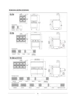
Страница 6: ...5 Dimensions and Burner Options ...

Страница 7: ...vice personnel with the proper equipment Connections Please check installer supplied intake pipes visually and or blow them out with compressed air to clear any dirt particles threading chips or other foreign matter before installing a service line When gas pressure is applied these particles can clog orifices All connections must be sealed with a joint compound suitable for LP gas and all connect...

Страница 8: ...ow connection downstream of the valve with a soapy water solution 6 Check the burner visually for blue flame There should be no yellow tips or soot If yellow tipping occurs call an authorized service person to adjust the burner air shutter Disclaimer All MARKET FORGE INDUSTRIES INC appliances are adjusted and tested before leaving the factory effectively matching them to sea level conditions Adjus...

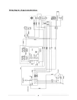
Страница 9: ...8 Wiring Diagram Range Convection Oven ...

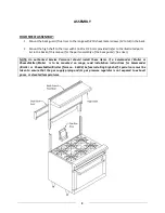
Страница 10: ...or the parts assembly of the back guard flue riser NOTE An authorized Service Personnel should install these items If a Salamander Broiler or CheeseMelter Broiler is to be mounted on range read installation instructions for Salamander Broiler or CheeseMelter Broiler form no S 6103 before installing high shelf Special care must be taken to ensure that the gas supply piping and or gas pressure regul...

Страница 11: ...urn the thermostat off open the door and allow the unit to cool Oven should be thoroughly washed using hot soapy water before being used TOP BURNERS RAISED GRIDDLE BROILER BROILER All top section burners are equipped with constant burning pilots These are to be manually lighted immediately after the gas is turned on and the system is checked for leaks Burner pilots are provided for each burner and...

Страница 12: ...rk igniter is not present apply a lit match to the pilot burner head 6 Continue to depress the safety valve button until the pilot remains lit when released 7 If pilot is extinguished repeat step 4 through 6 above 8 Turn the oven thermostat knob on and set to desired temperature setting watch to make sure the oven burner ignites from the pilot and that there are no yellow flames from the burner 9 ...

Страница 13: ...oven liner panels 4 Wash all the above with hot soapy water then reassemble 5 Baked on spills may be loosened and stubborn stains removed with ordinary household ammonia and scrubbing with a nylon pad in a cold oven only 6 Do not allow spray type oven cleaners to come into contact with the temperature probe in the oven 7 After cleaning the oven rinse well with 1 4 cup of vinegar to one quart of cl...

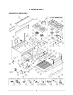
Страница 14: ...13 ILLUSTRATED PARTS Complete Range Exploded View ...

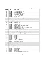
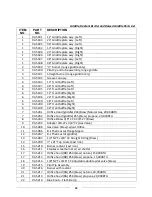
Страница 15: ... Plug used to block outlet on thermostat 12 93 5096 B J Thermostat Flange Nipple 13 93 5097 1 8 NPT x 3 16 CC 90º Adj Single Pilot Valve Brass 14 93 5098 Gas Valve Brass w out Orifice 15 93 5099 Orifice Hood 42 Open Burner Natural Gas 26 000BTU 15 93 5100 Orifice hood 53 Open burner propane 26 000BTU 16 93 5101 24 Valve cover 16 93 5102 36 Valve cover 16 93 5103 48 Valve cover 16 93 5104 60 Valve ...

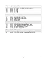
Страница 16: ...7 93 5137 60 Landing Ledge 37 93 5138 72 Landing Ledge 38 93 5139 Gas Pressure Regulator NAT 38 93 5140 Gas Pressure Regulator PROPANE 39 93 5123 Manual Ppark Igniter w Red Push Button 39 93 5141 Flue box assembly 40 93 5142 24 Stub back assembly 40 93 5143 36 Stub back assembly 40 93 5144 48 Stub back assembly 40 93 5145 60 Stub back assembly 40 93 5146 72 Stub back assembly 41 93 5147 24 Back gu...

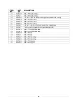
Страница 17: ... Fitting 53 93 5169 Left Side Panel 53 93 5170 Right Side Panel 53 93 5171 Safety Valve Bracket PN 2174 54 93 5172 Safety valve bracket PN 2174 B 55 93 5173 3 8 Aluminized tubing Specify length of tubing 56 93 5174 3 16 Aluminized tubing Specify length of tubing 56 93 5175 Oven flame spreader 26 1 2 oven 57 93 5176 Oven flame spreader 20 oven 58 93 5177 Top grate support bracket 59 93 5178 Wok rin...

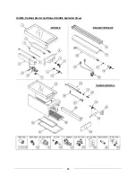
Страница 18: ...17 Griddle Radiant Broiler and Raised Griddle Exploded Views ...

Страница 19: ... 93 5200 48 Front baffle Right 6 93 5198 36 Front baffle Right 7 93 5201 Orifice Hood griddle 46 Brass Natural Gas 20 000BTU 7 93 5202 Orifice hood griddle 55 brass propane 20 000BTU 8 93 5203 Orifice Elbow 3 8 CC X 3 8 27 Brass 9 93 5204 Adapter 3 8 27 x 3 8 CC Gas Valve 10 93 5098 Gas Valve Brass w out Orifice 11 93 5096 B J Thermostat Flange Nipple 12 93 5207 B J Thermostat griddle 13 93 5093 1...

Страница 20: ...4 RRG 24 Valve cover 26 93 5225 RRG Grease can assy 27 93 5097 1 8 NPT x 3 16 CC 90º Adj Single Pilot Valve Brass 28 93 5227 Pilot tip and tube assembly range raised griddle 29 93 5228 RRG 12 Griddle plate assy 29 93 5229 RRG 24 Griddle plate assy 30 93 5230 RRG 12 Rack 30 93 5231 RRG 24 Rack 31 93 5232 RRG 12 Crumb tray 31 93 5233 RRG 24 Crumb tray 32 93 5234 RRG 12 Drip pan 32 93 5235 RRG 24 Dri...

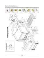
Страница 21: ...20 Convection Oven Exploded View ...

Страница 22: ...3 5008 Motor 18 93 5254 Motor Mount Weld Plate Assy 19 93 5255 Snorkel Tube Weld Assembly 20 93 5256 Manifold Tubing Manifold To Solenoid 3 8 Aluminized Tubing 21 93 5257 Straight Connector 3 8 CC X 1 8 NPT Male Thread 22 93 5258 Hex Head Shoulder Bolt 1 4 20 x 4 23 93 5259 Blower Baffle Cover 24 93 5260 Power Cord 25 93 5261 Straight Connector 3 8 CC X 3 8 NPT Male Thread 26 93 5262 RAM 4 Spark M...

Страница 23: ...0 000 B T U 37 93 5275 Switch Oven Door 38 93 5276 Burner Tubing 3 8 Diameter Aluminum 39 93 5277 Door Switch Bracket 40 93 5278 Oven Elbow Bracket 41 93 5120 U Burner Oven 42 93 5280 Solenoid End Bracket 43 93 5281 Solenoid Bracket 44 93 5282 Door Switch Bracket L H for RR 60 C ...

Отзывы: