Manitowoc Marine Q 1000 Скачать руководство пользователя страница 50


46


Refrigeration System


Self-Contained Charging Procedures


2.


Close the vacuum pump valve, the low side 
service valve, and the low side manifold gauge 
valve. 

Important


The charge is critical on all Manitowoc ice 
machines. Use a scale or a charging cylinder to 
ensure the proper charge is installed. 

3.


Open the high side manifold gauge valve, and 
backseat the high side service valve. 


1.


Be sure the toggle switch is in the OFF position. 

4.


Open the charging cylinder and add the proper 
refrigerant charge (shown on nameplate) 
through the discharge service valve. 
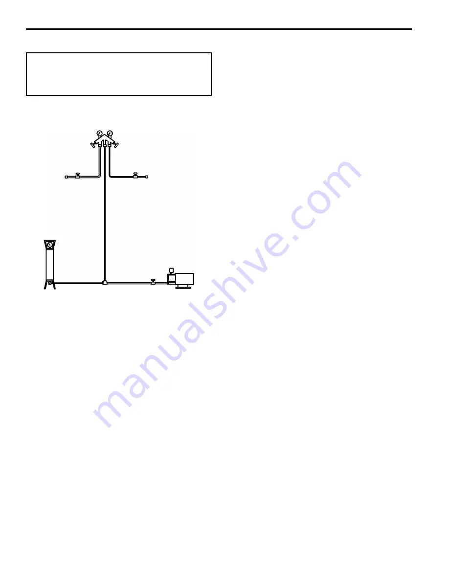


HIGH SIDE 
SERVICE 
VALVE


 SIDE 
VICE 

VALVE 

BACKSEATED 

FRONTSEATED 

OPEN 

CLOSED 

MANIFOLD SET 

OPEN 

CLOSED 

VACUUM PUMP/ 

RECOVERY UNIT

CHARGING 

CYLINDER 

SV1404B

5.


Let the system “settle” for 2 to 3 minutes. 

6.


Place the toggle switch in the ICE position. 

7.


Close the high side on the manifold gauge set. 
Add any remaining vapor charge through the 
suction service valve (if necessary). 

LOW

SER


NOTE: Manifold gauges must be removed properly 
to ensure that no refrigerant contamination or loss 
occurs. 


8.


Make sure that all of the vapor in the charging 
hoses is drawn into the ice machine before 
disconnecting the charging hoses. 


A.


Run the ice machine in freeze cycle. 

B.


Close the high side service valve at the ice 
machine. 

C.


Open the low side service valve at the ice 
machine. 

Charging Connections 

D.


Open the high and low side valves on the 
manifold gauge set. Any refrigerant in the 
lines will be pulled into the low side of the 
system. 

E.


Allow the pressures to equalize while the ice 
machine is in the freeze cycle. 

F.


Close the low side service valve at the ice 
machine. 

Remove the hoses from the ice machine and install 
the caps. 

Содержание Marine Q 1000

Страница 1: ... Manitowoc Ice Machine the dependability leader in ice making equipment and related products With proper installation care and maintenance your new Manitowoc Ice Machine will provide you with many years of reliable and economical performance Part Number 80 1211 3 7 00 ...

Страница 2: ... helpful and important information Throughout this manual you will see the following types of procedural notices Important Important boxes serve two functions They call the operator s attention to important information They also provide the service technician with information that may help perform a procedure more efficiently Disregarding this information may slow down the work NOTE Text set off a...

Страница 3: ... Board 18 Ice Thickness Probe Harvest Initiation How the Probe Works 20 Harvest Safety Limit Light 20 Freeze Time Lock In Feature 20 Maximum Freeze Time 20 Diagnosing Ice Thickness Control Circuitry Ice Machine Does Not Cycle Into Harvest When Water Contacts The Ice Thickness Probe 21 Ice Machine Cycles Into Harvest Before Water Contact With The Ice Thickness Probe 22 Water Level Control Circuitry...

Страница 4: ...ing Freeze Cycle Procedure 39 Freeze Cycle Suction Pressure High Checklist 40 Freeze Cycle Suction Pressure Low Checklist 40 How to Use the Refrigeration System Operational Analysis Tables 41 Refrigeration System Operational Analysis Table Dual TXV 42 Pressure Control Specifications and Diagnostics High Pressure Cutout HPCO Control 43 Cycle Time 24 Hour Ice Production Refrigerant Pressure Charts Q...

Страница 5: ... Up After Automatic Shut Off Harvest Water Purge The circuit board has an adjustable water purge in the harvest cycle This permits a 15 30 or 45 second purge cycle Auto Shut Off The ice machine remains off for 3 minutes before it can automatically restart The ice machine restarts steps 1 2 immediately after the delay period if the bin switch re closes prior to 3 minutes Safety Timers The control b...

Страница 6: ... 57 99 75 HOT GAS SOLENOID DUMP SOLENOID 81 WATER PUMP 77 80 21 22 WATER VALVE TB30 TB30 SELF CONTAINED MODELS Initial Start Up or Start Up After Automatic Shut Off 1 WATER PURGE Before the compressor starts the water pump and water dump solenoid are energized for 45 seconds to purge old water from the ice machine This ensures that the ice making cycle starts with fresh water The hot gas valve s i...

Страница 7: ...R FAN MOTOR AIR COOLED ONLY R R 45 46 50 PTCR BIN SWITCH LIGHT HARVEST LIGHT SAFETY LIMIT CODE LIGHT CLEAN LIGHT WATER LEVEL 49 63 62 66 65 69 ICE OFF CLEAN 67 68 1F 1C LOW D C VOLTAGE PLUG 62 1G TOGGLE SWITCH 68 67 69 66 62 VIEW FOR WIRING INTERNAL WORKING VIEW TB37 74 59 73 56 CONTACTOR COIL TERMINATES AT PIN CONNECTION TB30 TB30 TB30 TB30 L2 N SEE SERIAL PLATE FOR VOLTAGE 58 FUSE 7A TRANS 2 4 1...

Страница 8: ...COIL TERMINATES AT PIN CONNECTION TB30 TB30 TB30 TB30 L2 N SEE SERIAL PLATE FOR VOLTAGE 58 FUSE 7A TRANS 5 2 4 1 3 61 60 TB31 76 98 57 99 75 HOT GAS SOLENOID DUMP SOLENOID 81 WATER PUMP 77 80 21 22 WATER VALVE TB30 TB30 To pre chill the evaporator the compressor runs for 30 seconds prior to water flow The water fill valve remains on until the water level sensor closes for three continuous seconds ...

Страница 9: ...CONTACTOR COIL TERMINATES AT PIN CONNECTION TB30 TB30 TB30 TB30 L2 N SEE SERIAL PLATE FOR VOLTAGE 58 FUSE 7A TRANS 2 4 1 3 5 61 60 TB31 76 98 57 99 75 HOT GAS SOLENOID DUMP SOLENOID 81 WATER PUMP 77 80 21 22 WATER VALVE TB30 TB30 When sufficient ice has formed the water flow not the ice contacts the ice thickness probes After approximately 7 seconds of continual contact a harvest cycle is initiate...

Страница 10: ...ONTACTOR COIL TERMINATES AT PIN CONNECTION TB30 TB30 TB30 TB30 L2 N SEE SERIAL PLATE FOR VOLTAGE 58 FUSE 7A TRANS 2 4 1 3 5 61 60 TB31 76 98 57 99 75 HOT GAS SOLENOID DUMP SOLENOID 81 WATER PUMP 77 80 21 WATER VALVE 22 TB30 TB30 must be at the factory setting of 45 seconds for the fill valve to energize during the last 15 seconds of the Water Purge If set at less than 45 seconds the water fill val...

Страница 11: ...EW FOR WIRING INTERNAL WORKING VIEW TB37 74 59 73 56 CONTACTOR COIL TERMINATES AT PIN CONNECTION TB30 TB30 TB30 TB30 L2 N SEE SERIAL PLATE FOR VOLTAGE 58 FUSE 7A TRANS 2 4 1 3 5 61 60 TB31 76 98 57 99 75 HOT GAS SOLENOID DUMP SOLENOID 81 WATER PUMP 77 80 21 22 WATER VALVE TB30 TB30 The sliding sheet of cubes swings the water curtain out opening the bin switch This momentary opening and closing of ...

Страница 12: ...3 56 CONTACTOR COIL TERMINATES AT PIN CONNECTION TB30 TB30 TB30 L2 N SEE SERIAL PLATE FOR VOLTAGE 58 4 1 3 5 FUSE 7A TRANS 2 61 60 TB31 76 98 57 99 75 HOT GAS SOLENOID DUMP SOLENOID 81 WATER PUMP 77 80 21 22 WATER VALVE TB30 TB30 The ice machine remains off until enough ice is removed from the storage bin to allow the sheet of cubes to drop clear of the water curtain As the water curtain swings ba...

Страница 13: ...e working on electrical circuitry WIRING DIAGRAM LEGEND The following symbols are used on all of the wiring diagrams Internal Compressor Overload Some models have external compressor overloads TB Terminal Board Connection Terminal board numbers are printed on the actual terminal board Wire Number Designation The number is marked at each end of the wire Multi Pin Connection Electrical Box Side Comp...

Страница 14: ...INATES AT PIN CONNECTION CONTACTOR COIL 5 21 22 WATER VALVE 35 TB 88 87 RH HOT GAS SOLENOID L1 49 48 35 TB30 TB30 1C 1F ICE THICKNESS PROBE LOW D C VOLTAGE PLUG WATER LEVEL PROBE BIN SWITCH 62 63 64 65 66 66 67 HARVEST LIGHT SAFETY LIMIT CODE LIGHT BIN SWITCH LIGHT 68 VIEW FOR WIRING 66 67 68 69 62 TOGGLE SWITCH CLEAN OFF ICE INTERNAL WORKING VIEW WATER LEVEL LIGHT CLEAN LIGHT 1G AUCS DISPENSE TIM...

Страница 15: ...ds it open After the water curtain is held open for 7 seconds the ice machine shuts off 1 If the bin switch light is on with the water curtain closed the fuse is good The ice machine remains off until enough ice is removed from the storage bin to allow the sheet of cubes to drop clear of the water curtain As the water curtain swings back to the operating position the bin switch closes and the ice ...

Страница 16: ...n the harvest cycle time reaches 3 5 minutes and the bin switch is not closed the ice machine stops as though the bin were full 1 Disconnect the bin switch wires to isolate the bin switch from the control board 2 Connect an ohmmeter to the disconnected bin switch wires Set the ohmmeter to the 10 000 ohm scale Water curtain is put back on If the bin switch closes prior to reaching the 3 5 minute po...

Страница 17: ...ounded and the compressor should be replaced Determine if the Compressor is Seized Check the amp draw while the compressor is trying to start COMPRESSOR DRAWING LOCKED ROTOR The two likely causes of this are Defective starting component Mechanically seized compressor To determine which you have 1 Install high and low side gauges 2 Try to start the compressor 3 Watch the pressures closely A If the ...

Страница 18: ...arge and suction pressures to be somewhat equalized prior to the compressor starting To assure equalization of pressures the hot gas valve and HPR valve on remotes will energize for 45 seconds prior to compressor starting The hot gas valve and HPR valve on remotes remains on for an additional 5 seconds while the compressor is starting 2 When starting the compressor the contactor closes and the PTC...

Страница 19: ...e ice machine restarts provided the three minute delay period is complete If the PTCR is still warm say 160 F 71 1 C when the compressor starts it will take only 125 to 50 seconds before its temperature reaches 260 F 126 6 C and current flow is stopped This decreased time may be insufficient to start the compressor During Start Up First 25 1 0 Seconds SV1506 SV1507 L1 L2 CONTACTOR CONTACTS C R S R...

Страница 20: ...e attempting to start the compressor The hot gas valve and HPR valve on remotes energizes for 45 seconds before the compressor starts and remains on 5 seconds after the compressor starts Make sure this is occurring before assuming that the PTCR is bad CHECKING THE PTCR WARNING Disconnect electrical power to the entire ice machine at the building electrical disconnect box before proceeding 1 Visual...

Страница 21: ...toggle switch 3 Check across the toggle switch terminals using a calibrated ohm meter Note where the wire numbers are connected to the switch terminals or refer to the wiring diagram to take proper readings Switch Setting Terminals Ohm Reading 66 62 Open ICE 67 68 Closed 67 69 Open 66 62 Closed CLEAN 67 68 Open 67 69 Closed 66 62 Open OFF 67 68 Open 67 69 Open 4 Replace the toggle switch if ohm re...

Страница 22: ...ESS PROBE 3 16 CONNECTION DC LOW VOLTAGE ELECTRICAL PLUG NUMBERS MARKED ON WIRES HARVEST LIGHT SAFETY LIMIT CODE LIGHT RED BIN SWITCH LIGHT GREEN AC LINE VOLTAGE ELECTRICAL PLUG NUMBERS MARKED ON WIRES N 115V L2 208 230V L1 PRIMARY POWER SUPPLY SV1588 WATER LEVEL PROBE WATER LEVEL PROBE LIGHT GREEN CLEAN LIGHT YELLOW 1F 1C Q1800 ONLY 20 Control Board ...

Страница 23: ...rical components including the ice machine sequence of operation Prior to diagnosing you must understand how the inputs affect the control board operation Refer to specific component specifications inputs wiring diagrams and ice machine sequence of operation sections for details As an example refer to Ice Thickness Probe in the component specifications section of this manual for information relati...

Страница 24: ...utes the harvest light will come on to indicate that water is in contact with the probe but the ice machine will stay in the freeze cycle After the six minutes are up a harvest cycle is initiated This is important to remember when performing diagnostic procedures on the ice thickness control circuitry To allow the service technician to initiate a harvest cycle without delay this feature is not use...

Страница 25: ...trol circuitry is functioning properly The ice machine is in a six minute freeze time lock in Verify step 1 of this procedure was followed correctly The harvest light does not come on Proceed to Step 3 below Step 3 Disconnect the ice thickness probe from the control board at terminal 1C Clip the jumper wire leads to terminal 1C on the control board and any cabinet ground Monitor the harvest light ...

Страница 26: ...vest light Step 2 Step 2 Disconnect probe from control board terminal 1C Monitoring of Harvest Light Correction The harvest light stays off and the ice machine remains in the freeze sequence The ice thickness probe is causing the malfunction Verify that the Ice Thickness probe is adjusted correctly The harvest light comes on and 6 10 seconds later the ice machine cycles from freeze to harvest The ...

Страница 27: ...ure limits the water inlet valve to a six minute on time Regardless of the water level probe input the control board automatically shuts off the water inlet valve if it remains on for 6 continuous minutes This is important to remember when performing diagnostic procedures on the water level control circuitry The water inlet valve turns off after water contacts the water level probe for 3 continuou...

Страница 28: ...t a jumper from the water level probe to any cabinet ground Important For the test to work properly you must wait until the freeze cycle starts prior to connecting the jumper wire If you restart the test you must disconnect the jumper wire restart the ice machine step 1 and then reinstall the jumper wire after the compressor starts Step 2 WATER LEVEL LIGHT BIN SWITCH LIGHT HARVEST SAFETY LIMIT LIG...

Страница 29: ...onnecting the jumper wire restarting the ice machine step 1 and then reinstalling the jumper wire to terminal 1F after the compressor starts Step 3 HARVEST SAFETY LIMIT LIGHT WATER LEVEL LIGHT BIN SWITCH LIGHT CLEAN LIGHT YELLOW GREEN GREEN RED 1C 1G GROUND JUMPER 1F SV1588 Step 3 Jumper wire connected from control board terminal 1F to ground The Water Inlet Valve Solenoid Coil is Is water flowing...

Страница 30: ...ange any parts Energized no on or off Or Proceed to step 3 De Energized Step 3 Leave the ice machine run then disconnect the water level probe from control board terminal 1F Important For the test to work properly you must wait until the freeze cycle starts prior to disconnecting the water level probe If you restart the test you must reconnect the water level probe restart the ice machine step 1 a...

Страница 31: ...closed if primary power voltage is present at terminals 55 and 56 on the control board 3 Verify control board fuse is OK If the bin switch light functions the fuse is OK 4 Verify the bin switch functions properly A defective bin switch can falsely indicate a full bin of ice 5 Verify ICE OFF CLEAN toggle switch functions properly A defective toggle switch may keep the ice machine in the OFF mode 6 ...

Страница 32: ...Sequence of Operation Q1800 REFRIGERATION TUBING SCHEMATICS DRIER RECEIVER COMPRESSOR WATER COOLED CONDENSER STRAINER EXPANSION VALVE EXPANSION VALVE EVAPORATOR HEAT EXCHANGE HOT GAS SOLENOID VALVES SV1512 Q1800 Self Contained Water Cooled Models ...

Страница 33: ...the problem loose bulb was corrected when the technician properly mounted the bulb of the replacement expansion valve The service technician s failure to check the expansion valve bulb for proper mounting an external check resulted in a misdiagnosis and the needless replacement of a good expansion valve 3 An ice machine that is low on charge may cause a good expansion valve to starve If a service ...

Страница 34: ...F 32 2 C room with 70 F 21 2 C water 1 Determine the ice machine operating conditions Air Temp Entering Condenser ____ Air Temp Around Ice Machine ____ Water Temp Entering Sump Trough ____ 2 Refer to the appropriate 24 Hour Ice Production Chart Use the operating conditions determined in Step 1 to find published 24 hour ice production ______ 3 Perform an actual ice production check Use the formula ...

Страница 35: ...s Possible Problem Corrective Action Water area evaporator is dirty Clean as needed Water inlet pressure not between 20 and 80 psi Install a water regulator valve or increase the water pressure Incoming water temperature is not between 35 F 1 7 C and 90 F 32 2 C If too hot check the hot water line check valves in other store equipment Water filtration is plugged if used Install a new water filter ...

Страница 36: ...n ice formation that is extremely thin on top could be caused by a hot water supply a dump valve leaking water a faulty water fill valve a low refrigerant charge etc Important Keep the water curtain in place while checking the ice formation pattern to ensure no water is lost 1 Normal Ice Formation Ice forms across the entire evaporator surface At the beginning of the freeze cycle it may appear tha...

Страница 37: ...orator circuits These circuits operate independently from each other Therefore one may operate properly while the other is malfunctioning Example If the left expansion valve is starving it may not affect the ice formation pattern on the entire right side of the evaporator OUTLET ICE OUTLET OUTLET INLET Extremely Thin Ice Formation at Evaporator Inlet SV1575 INLET INLET 4 Spotty Ice Formation SV157...

Страница 38: ...densers water loss to the ice machine etc The safety limits protect the ice machine primarily the compressor from external failures by stopping ice machine operation before major component damage occurs The safety limit system is similar to a high pressure cut out control It stops the ice machine but does not tell what is wrong The service technician must analyze the system to determine what cause...

Страница 39: ...efective water regulating valve Water regulating valve out of adjustment Refrigeration system Non Manitowoc components Improper refrigerant charge Defective hot gas valve Defective compressor TXV starving or flooding check bulb mounting Non condensables in refrigeration system Plugged or restricted high side refrigerant lines or component SAFETY LIMIT NOTES Because there are many possible external...

Страница 40: ... thickness probe dirty Bin switch defective Premature harvest Refrigeration system Non Manitowoc components Water regulating valve dirty defective Improper refrigerant charge Defective hot gas valve TXV flooding check bulb mounting SAFETY LIMIT NOTES Because there are many possible external problems do not limit your diagnosis to only the items listed in this chart A continuous run of 100 harvests...

Страница 41: ...ve application and rebuild kits If replacement is necessary Use only original Manitowoc replacement parts This is an indication something is wrong as the hot gas valve inlet did not cool down during the freeze cycle If the compressor dome is also entirely hot the problem is not a hot gas valve leaking but rather something causing the compressor and the entire ice machine to get hot The inlet of th...

Страница 42: ...or the ice machine s operating conditions Freeze Cycle Discharge Pressure High Checklist Possible Cause Check Correct Improper installation See Installation Visual Inspection Checklist on page 7 10 Restricted condenser water flow water cooled models Low water pressure 20 psi min High inlet water temperature 90 F 32 2 C max Dirty condenser Dirty defective water regulating valve Water regulating val...

Страница 43: ...g Published freeze cycle Published freeze cycle suction pressure Pressure charts for ice machine model being checked Using operating conditions from Step 1 determine published freeze cycle time and published freeze cycle suction pressure time 9 6 10 6 40 20 minutes PSIG Published Freeze Cycle Time minutes 2B Compare the published freeze cycle time and published freeze cycle suction pressure Develo...

Страница 44: ...e Cycle Suction Pressure Low Checklist Possible Cause Check Correct Improper installation See Installation Visual Inspection Checklist Discharge pressure Discharge pressure is too low and is affecting low side See Freeze Cycle Discharge Pressure Low Checklist Improper refrigerant charge Undercharged Wrong type of refrigerant Other Non Manitowoc components in system Improper water supply over evapo...

Страница 45: ...d or supporting material was not analyzed correctly Final Analysis The column with the highest number of check marks identifies the refrigeration problem COLUMN 1 HOT GAS VALVE LEAKING Normally a leaking hot gas valve can be repaired with a rebuild kit instead of changing the entire valve Rebuild or replace the valve as required COLUMN 2 LOW CHARGE TXV STARVING Normally a starving expansion valve ...

Страница 46: ... freeze cycle Compare temperatures of compressor discharge line and both hot gas valve inlets Comp Disc ______ F Left gas inlet ______ F Right gas inlet ______ F One hot gas valve inlet is Hot Both hot gas valve inlets are cool enough Both hot gas valve inlets are cool enough Both hot gas valve inlets are cool enough to hold hand on to hold hand on and to hold hand on and and approaches the temper...

Страница 47: ...ok voltmeter in parallel across the HPCO leaving wires attached 4 On water cooled models close the water service valve to the water condenser inlet On self contained air cooled and remote models disconnect the fan motor 5 Set ICE OFF CLEAN switch to ICE 6 No water or air flowing through the condenser will cause the HPCO control to open because of excessive pressure Watch the pressure gauge and rec...

Страница 48: ... 1520 80 26 7 1780 1680 1520 90 32 2 1760 1670 1510 100 37 8 1750 1660 1490 1 Based on average ice slab weight of 13 0 14 12 lb 2 Regular cube derate is 7 Condenser 90 32 2 Air Temperature Around Ice Machine Water Water Temperature F C Consumption 50 10 0 70 21 1 90 32 2 Gal 24 hours 2000 2670 7750 1 Water regulating valve set to maintain 240 PSIG discharge pressure Operating Pressures Air Temp Fr...

Страница 49: ... liquid line filter drier to prevent voiding the warranty CONNECTIONS 1 Suction side of the compressor through the suction service valve 2 Discharge side of the compressor through the discharge service valve MANIFOLD SET OPEN OPEN BACKSEATED BACKSEATED LOW SIDE SERVICE VALVE HIGH SIDE SERVICE VALVE CHARGING CYLINDER VACUUM PUMP RECOVERY UNIT OPEN CLOSED Recovery Evacuation Connections SV1404A 3 Op...

Страница 50: ...for 2 to 3 minutes 6 Place the toggle switch in the ICE position 7 Close the high side on the manifold gauge set Add any remaining vapor charge through the suction service valve if necessary LOW SER NOTE Manifold gauges must be removed properly to ensure that no refrigerant contamination or loss occurs 8 Make sure that all of the vapor in the charging hoses is drawn into the ice machine before dis...

Страница 51: ...ot available inspect the compressor oil 1 Remove the refrigerant charge from the ice machine 2 Remove the compressor from the system 3 Check the odor and appearance of the oil 4 Inspect open suction and discharge lines at the compressor for burnout deposits 5 If no signs of contamination are present perform an acid oil test Check the chart below to determine the type of cleanup required Contaminat...

Страница 52: ...r on self contained models 1 hour on remotes NOTE You may perform a standing vacuum test to make a preliminary leak check You should use an electronic leak detector after system charging to be sure there is no leak 5 Charge the system with the proper refrigerant to the nameplate charge 6 Operate the ice machine Severe System Contamination Cleanup Procedure 1 Remove the refrigerant charge 2 Remove ...

Страница 53: ... next page Clamp down on the tubing until the pinch off is complete NOTE You may perform a standing vacuum test to make a preliminary leak check You should use an electronic leak detector after system charging to be sure there is no leak 12 Charge the system with the proper refrigerant to the nameplate charge WARNING Do not unsolder a defective component Cut it out of the system Do not remove the ...

Страница 54: ...50 Refrigeration System FIG A PINCHING OFF TUBING TYPICAL PRESSURE CONTROL SHOWN PINCH OFF TOOL US D HERE E SEE FIG A AND FIG B FIG B RE ROUNDING TUBING Using Pinch Off Tool SV1406 ...

Страница 55: ...every harvest cycle These filter driers have a very high moisture removal capability and a good acid removal capacity The size of the filter drier is important The refrigerant charge is critical Using an improperly sized filter drier will cause the ice machine to be improperly charged with refrigerant Important Driers are covered as a warranty part The drier must be replaced any time the system is...

Страница 56: ...rocess refrigerant to new product specifications see below by means which may include distillation A chemical analysis of the refrigerant is required after processing to be sure that product specifications are met This term usually implies the use of processes and procedures available only at a reprocessing or manufacturing facility Chemical analysis is the key requirement in this definition Regar...

Страница 57: ...t edition specifications 3 Recovered or Recycled Refrigerant Must be recovered or recycled in accordance with current local state and federal laws Must be recovered from and re used in the same Manitowoc product Re use of recovered or recycled refrigerant from other products is not approved Recycling equipment must be certified to ARI Standard 740 latest edition and be maintained to consistently m...

Страница 58: ...ace a faulty component be sure you have all of the needed components at the site Remove new system component plugs and caps just prior to brazing Be prepared to connect a vacuum pump immediately after brazing 4 Are there any special procedures required if a POE system is diagnosed with a refrigerant leak For systems found with positive refrigerant system pressure no special procedures are required...

Страница 59: ...HFC usage Once designated and calibrated if needed for HFC use this equipment should be used specifically with HFC refrigerants only 8 Do I have to recover HFC refrigerants Yes Like other refrigerants government regulations require recovering HFC refrigerants 9 Will R 404A or R 134A separate if there is a leak in the system No Like R 502 the degree of separation is too small to detect 10 How do I ...

Страница 60: ...56 Refrigeration System Section 7 ...

Страница 61: ......

Страница 62: ...out notice MANITOWOC ICE INC 2110 South 26th Street P O Box 1720 Manitowoc WI 54221 1720 Phone 920 682 0161 We reserve the right to make product improvements at any time Fax 920 683 7585 Web Site www manitowocice com 2000 Manitowoc Ice Inc Litho in U S A ...

Отзывы: