background image

4

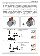
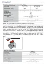
The damper can be equipped with electric actuating mechanism. There are several actuators: BELIMO BFL, BFN230-T (version .40)

or BFL, BFN24-T (version .50). After connection to the power supply AC/DC 24V or AC230V, the actuating mechanism displaces the

damper blade into operation position "OPEN". At the same time is pre-stretched back spring inside the actuator. When the actuator is

under voltage (on power supply), the damper´s blade is in the position "OPEN". The back spring is pre-stretched. Time needed for full

opening of the damper blade from the position "CLOSED" to the position "OPEN" is maximum 140s (for type BF) or 60s (for type BFL,

BFN).  If  the  power  supply  of  the  actuator  is  cut  off  (due  to  disconnection  of  power  supply,  or  pressing  the  reset  button  on  the

thermo-electrical  starting  mechanism  BAT  (thermal  fuse),  the  back  spring  displaces  the  damper´s  blade  into  the  safety  position

"CLOSED". The time needed for displacing of the blade from the position "OPEN" to the position "CLOSE" takes maximal 20s. In the

case that the power supply is restored again (the blade can be in arbitrary position), the actuator starts re-displacing the damper´s

blade position into the emergency position "OPEN". The thermos-electrical mechanism BAT, which contains two thermal fuses Tf1

and Tf2, is a part of actuator. These fuses are activated when tempe72°C has been exceeded. The fuse Tf1 measures the

temperature  in  the  outside  of  the  damper  and  Tf2  measure  the  temperature  inside  the  air  duct.  Both  fuses,  they  are  in  serial

connection. It means in fact, that when one of them is activated, the power supply of the actuator is cut-off and the actuator displaces

the blade in safety position "CLOSED". The signalization of damper position "OPEN" or "CLOSED" is provided by two limit switches,

which are built-in inside the actuator. The thermal fuse BAT can be also installed separately, into the spiral air duct, outside of the fire

damper (order code for this option is .4V or .5V - see the product code).

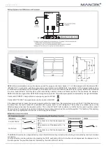
1 2

S3

S1 S2

S5

S4

S6

Connection via safety isolating transformer.

<5°

<80°

BAT

Tf

Tf

LED

Parallel connection of other actuators possible. Observe the performance data. 

Combination of power supply voltage and safety extra-low voltage not permitted

at the both auxiliary switches.

~

- +

Application examples for integration

into monitoring and control systems

or into bus networks can be found in

the documentation of the connected

communication and power supply unit.

1 = blue

2 = brown

S1 = violet

S2 = red

S3 = white

S4 = orange

S5 = pink

S6 = grey

1 2

S3

S1 S2

S5

S4

S6

N L1

Caution: Power supply voltage! 

<5°

<80°

BAT

Tf

Tf

LED

The actuator must be protected by a fuse that does not exceed 16 A. 

Parallel connection of other actuators possible. Observe the performance data. 

Combination of power supply voltage and safety extra-low voltage not permitted

at the both auxiliary switches. 

1 = blue

2 = brown

S1 = violet

S2 = red

S3 = white

S4 = orange

S5 = pink

S6 = grey

Содержание FDMS Series

Страница 1: ......

Страница 2: ...t in addition to the standard design In addition to activation by means of thermal fuses or links in the actuator the damper must also be activated by smoke detectors and or heat detectors that have b...

Страница 3: ...e for camera For others service works there must by installed inspection door externally on the duct next to the fire damper The damper is equipped with additional collar around the position of the bl...

Страница 4: ...ation of the shutting device is not activated if the temperature does not exceed 70 C Design with mechanical control can be complemented with a limit switch signaling the damper s blade position CLOSE...

Страница 5: ...ceeded The fuse Tf1 measures the temperature in the outside of the damper and Tf2 measure the temperature inside the air duct Both fuses they are in serial connection It means in fact that when one of...

Страница 6: ...erordinate system controls via the same wiring to the actuating mechanism To allow more simple connection the actuator BFL BFN 24 T ST is equipped with two connecting plugs one with three jacks and on...

Страница 7: ...ntrol LED OPEN damper blade in emergency position OPEN Control LED CLOSE damper blade in safety position CLOSED If the damper does not reach the required position within the preset time the appropriat...

Страница 8: ...n 5 5 VA III safe small voltage IP 30 0 50 C Terminals for conductor 2 x 1 5 mm c aM c aS for the actuator BFL 86mm BFN 110mm the height of the actuator BFL 48mm BFN 52mm D 70 2 164 70 61 D D1 220 41...

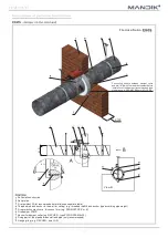
Страница 9: ...vice works the external access door inspection hole must be installed on the air duct next to the fire damper The distance between the fire damper and the construction wall ceiling must be minimum 75...

Страница 10: ...ric Solid ceiling construction t 125mm for aera ted concrete Wet Mortar or gypsum Outside solid ceiling construction with t 125mm for aerated concrete insulation of the pipe between wall and damper ma...

Страница 11: ...ht Fire protection mastic min thickness 1mm e g PROMASTOP P or K Fire damper FDMS Anchor for damper collar e g FISCHER type ZYKON FZA M8x30 Fixing part of the pipe between wall and pipe only recommend...

Страница 12: ...11 Fire classification 96 47 47 96 96...

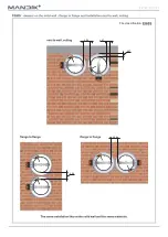
Страница 13: ...een wall and pipe insulation fulfil with fire resistant sealant before instalation of the insulation recommended type of sealant see instalation instructions of the insulation contractor Installation...

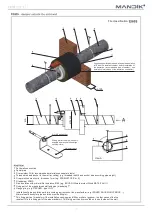
Страница 14: ...hickness 1mm e g PROMASTOP P or K Fire damper FDMS Anchor for damper collar threaded rod and nuts M8 or e g anchor FISCHER type KD8 Fixing part of the pipe between wall and pipe only recommended Hangi...

Страница 15: ...14 Fire classification 96 47 47 96 96...

Страница 16: ...een wall and pipe insulation fulfil with fire resistant sealant before instalation of the insulation recommended type of sealant see instalation instructions of the insulation contractor Installation...

Страница 17: ...HER type ZYKON FZA M8x30 Fixing part of the pipe between wall and pipe mandatory Hanging ring e g FISCHER type LGS Fire classification View A Nut M8 and anchor 8 fixing part of the pipe see only examp...

Страница 18: ...17 Fire classification 96 47 47 96 96...

Страница 19: ...Hanging ring e g FISCHER type LGS 150 Installation of pipe insulation perform according instructions of the manufacturer e g ISOVER ROCKWOOL PAROC Minimal wool density for pipe insulation must be 66kg...

Страница 20: ...d rod and nuts M8 Fixing part of the pipe between wall and pipe only recommended Hanging ring e g FISCHER type LGS Installation ring View B D Fire classification 100 Before instalation of the fire res...

Страница 21: ...ght Fire protection mastic min thickness 1mm e g PROMASTOP P or K Fire damper FDMS Pipe insulation with minimal fire resistance EI60 e g ISOVER Ultimate protect Wired MAT 4 0 ALU1 Fixing part of the p...

Страница 22: ...The insulation of the pipe must cover the damper collar from back side 1 0 10 0 100 0 10 100 1000 10000 Air flow m3 h Pressure drop Pa 200 14000 Air flow m3 h Pressure drop Pa 200 14000 Insulation ed...

Страница 23: ...43 45 2 5 15 22 28 33 37 41 44 47 49 2 2 12 20 26 32 36 40 43 46 49 2 2 6 14 21 27 32 36 39 43 46 2 2 2 6 13 19 24 28 32 36 39 2 2 2 2 2 7 13 18 22 25 29 2 2 2 5 10 13 16 19 22 24 26 2 2 9 15 20 24 27...

Страница 24: ...36 39 43 46 49 2 2 6 14 21 26 31 35 39 42 45 2 2 2 5 12 18 23 28 32 35 39 2 2 2 2 2 7 12 17 21 25 28 2 2 2 4 9 12 15 18 21 23 25 2 2 8 14 19 23 27 30 32 35 37 2 4 13 20 25 30 33 37 40 42 45 2 5 14 22...

Страница 25: ...38 42 45 48 51 2 2 8 16 23 29 34 38 41 45 48 2 2 2 8 15 21 26 30 34 38 41 2 2 2 2 3 9 15 19 24 27 31 2 2 2 8 12 16 19 22 24 26 28 2 3 11 18 23 27 30 33 36 38 40 2 7 16 23 29 33 37 40 43 46 48 2 8 18 2...

Страница 26: ...made of sheet brass thickness 0 5 mm Fasteners are made of galvanized steel The appliance is constructed and preset by the manufacturer its operation is dependent on proper installation and adjustment...

Страница 27: ...can be operated manually and fixed in any required position Release of the locking mechanism can be achieved manually or automatically by applying the supply voltage It is recommended to provide peri...

Страница 28: ...158 100 130 95 178 100 175 105 198 100 175 115 223 100 175 127 248 100 175 140 278 100 175 155 313 100 175 173 353 100 175 193 398 125 225 220 448 125 225 245 498 125 225 270 558 125 225 300 628 125 2...

Страница 29: ...28...

Страница 30: ...29...

Страница 31: ...30...

Страница 32: ...reserves the right for innovations of the product For actual product information see www mandik com MAND K a s Dob sk 550 26724 Hostomice Czech Republic Tel 420 311 706 706 E Mail mandik mandik cz ww...

Отзывы:

Похожие инструкции для FDMS Series