8
1
2
S3
S1 S2
S5
S4
S6
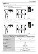
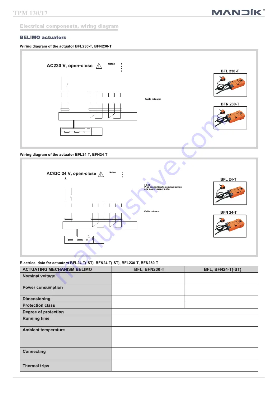
N L1
Caution: Power supply voltage!
<5°
<80°
BAT
Tf
Tf
LED
The actuator must be protected by a fuse that does not exceed 16 A.
Parallel connection of other actuators possible. Observe the performance data.
Combination of power supply voltage and safety extra-low voltage not permitted
at the both auxiliary switches.
1 = blue
2 = brown
S1 = violet
S2 = red
S3 = white
S4 = orange
S5 = pink
S6 = grey
1
2
S3
S1 S2
S5
S4
S6
Connection via safety isolating transformer.
<5°
<80°
BAT
Tf
Tf
LED
Parallel connection of other actuators possible. Observe the performance data.
Combination of power supply voltage and safety extra-low voltage not permitted
at the both auxiliary switches.
~
-
+
Application examples for integration
into monitoring and control systems
or into bus networks can be found in
the documentation of the connected
communication and power supply unit.
1 = blue
2 = brown
S1 = violet
S2 = red
S3 = white
S4 = orange
S5 = pink
S6 = grey
AC 230 V 50/60 Hz
AC 24 V 50/60 Hz
DC 24 V
- motoring
- holding
3,5/5 W
1,1/2,1 W
2,5/4 W
0,8/1,4 W
6,5/10 VA (Imax 4 A @ 5 ms)
4/6 VA (Imax 8,3 A @ 5 ms)
II
III
IP 54
- motor
- spring return
<60 s
~ 20 s
- normal duty
- safety duty
- non-operating temperature
- 30 °C … 55 °C
The safe position will be attained up to max. 75°C
- 40 °C … 55 °C
- motor
- auxiliary switch
cable 1 m, 2 x 0,75 mm
²
(BFL/BFN 24-T-ST) with 3-pin plug-in connectors
cable 1 m, 6 x 0,75 mm
²
(BFL/BFN 24-T-ST) with 6-pin plug-in connectors
duct outside temperature 72 °C
duct inside temperature 72 °C
Содержание FDML
Страница 1: ......


