background image

18

Dimensions are checked using common gauges according to the standards for not tolerated dimensions applied in air conditioning
sector. In-process inspections of parts and main dimensions are carried out according to drawing documentation.

After workshop assembly 100% functional test of closing device and electric elements is carried out.

Dampers are transported in bulk in covered transport means without direct weathering effects, without strong impacts and ambient
temperature must not 50°C. If customer requires other packaging it will not be returnable and price of such a packaging
is not included in the price.
Dampers shall be considered as accepted unless it is specified otherwise in particular order.
During handling within transport and storage dampers must be protected from mechanical damage. Dampers must be stored in
roofed objects with environment without aggressive vapours, gases and dust. Temperature scope in such objects must be within
- 5 to + 40°C and relative humidity max. 80 %.
The delivery means complete Multi blade fire damper and warranty card with inspection stamp (warranty card is attached to invoice).

Manufacturer provides 24 month-guarantee from dispatching date.
Guarantee for FDML damper provided by the manufacturer becomes void if any non professional handling with closing mecha-
nism and control device by not trained persons has been performed, after dismantling electrical elements, i.e. limit switches, servo
drives, optical smoke detectors and thermo-electric actuators. Guarantee also becomes void when damper is used for other than
intended use and in working conditions not allowed by this standard or if it was damaged mechanically during handling.
If any damage occurs during the transport it is necessary to make a report during unloading with transport company for future claims.

Assembly, maintenance and serviceability checks may be performed only by persons capable for such activities, i.e. "AUTHORIZED
PERSONS" trained by the manufacturer. Training is organised and carried out by MANDÍK, a.s. who issues "CERTIFICATE" on
professional qualification with validity 5 years and its prolongation must be provided by "AUTHORIZED PERSON" itself directly at
trainer premises.
When terminates validity of the CERTIFICATE such CERTIFICATE becomes void and it is discarded from trainer files.
Only qualified persons can be trained who then answer for performed works.
Damper must be installed with respecting of all safety standards and regulations.
Closing mechanism and blade seating faces must be protected from clogging to ensure reliable functioning of the damper.

Before  putting  the  damper  into  operation  serviceability  checks  and  functional  tests  must  be  carried  out  including  testing  of
functionality of all electrical elements. After putting into operation these serviceability checks must be carried out 2 times a year
at least. If no defect is found during two subsequent serviceability checks, it is possible to carry out such operational checks once
a year.
If dampers are found as non-functional due to any reason, they must be clearly marked. User is obliged to ensure that the damper
is put in conditions in which it is able to fulfil its function and before this user must ensure fire protection in some other sufficient
way. Results of regular inspections and checks, found deficiencies and all important facts related to functioning of the damper
must be recorded in the FIRE JOURNAL and reported to user immediately.

Before putting damper into serviceable condition after assembly and subsequent serviceability checks the following inspections
must be carried out:

Visual check of correct walling-in of the damper, thermal fuse, closing mechanisms and blade seating faces.

Functionality of closing mechanism is done as follows:

Press reset button on the thermo-electric actuator accessible through the hole in cover plate and check dislocation of blade
to the position "CLOSED" and signalling of positions "OPEN -CLOSED".

Serviceability checks of optical smoke detector are performed by manufacturer (LITES a.s. Liberec) or authorized company staff
with  relevant  electro-technical  qualification  and  who  were  demonstrably  trained  by  the  manufacturer.  Serviceability  checks  of
detectors are carried out within serviceability checks of fire dampers min. once a year.

Spare parts are supplied only on the basis of orders.

Содержание FDML

Страница 1: ......

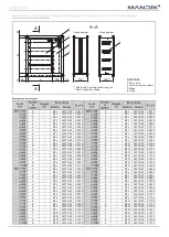
Страница 2: ...ng for design manufacture delivery storage assembly operation maintenance and serviceability checks Description 2 Design 3 Material 3 Dimensions and weight 4 Electrical components wiring diagram 8 Installation and placement 13 Checks 18 Tests 18 Logistic data 18 Guarantee 18 Assembly 18 Putting into operation and serviceability checks 18 Spare parts 18 Nameplate 19 ...

Страница 3: ...re stop SEALANT min thickness 1 mm i e HILTI Acrylic sealant CFS S ACR and fire stop COATING min thickness 1 mm for instance HILTI Firestop coating CFS CT Rigid wall or plasterboard structure min thickness 100 mm EI 90 S E 120 S CE certification according to EN 15650 Tested according to EN 1366 2 Classified according to EN 13501 3 A1 Fire resistance EI 90 S E 120 S Damper casing air leakage catego...

Страница 4: ...opening of damper blade from CLOSED position to OPEN is max 60s If servo powering is interrupted by loss of supply voltage or by pressing reset button on thermo electric actuator BAT or when temperature exceeds 72 C the check spring sets damper blade to emergency position CLOSED Time for complete changeover of damper blade from OPEN position to CLOSED is max 20 s If supply voltage is restored the ...

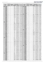
Страница 5: ...340TA 05 0 1606 2 BFL 340TA 03 0 0360 2 BFL 340TA 03 0 0444 2 BFL 340TA 03 0 0370 2 BFL 340TA 03 0 0457 3 BFL 340TA 03 0 0456 3 BFL 340TA 03 0 0562 3 BFL 340TA 03 0 0552 3 BFL 340TA 03 0 0681 4 BFL 340TA 03 0 0574 4 BFL 340TA 03 0 0708 4 BFL 340TA 03 0 0681 4 BFL 340TA 03 0 0840 4 BFL 340TA 03 0 0723 4 BFL 340TA 03 0 0892 5 BFL 340TA 03 0 0809 5 BFL 340TA 03 0 0998 5 BFL 340TA 03 0 0873 5 BFL 340T...

Страница 6: ... 340TA 05 0 1429 3 BFN 340TA 05 0 1116 6 BFN 340TA 05 0 1557 3 BFN 340TA 05 0 1352 6 BFN 340TA 05 0 1621 4 BFN 340TA 05 0 1404 7 BFN 340TA 05 0 1748 4 BFN 340TA 05 0 1666 7 BFN 340TA 05 0 1908 4 BFN 340TA 05 0 1771 8 BFN 360TA 12 0 1940 5 BFN 360TA 12 0 1981 8 BFN 360TA 12 0 2099 5 BFN 360TA 12 0 2138 2 BFL 340TA 03 0 0612 5 BFN 360TA 12 0 2243 2 BFL 340TA 03 0 0630 6 BFN 360TA 12 0 2295 3 BFL 340...

Страница 7: ...6 BF 360TA 12 0 2751 3 BFN 340TA 05 0 1627 6 BF 360TA 12 0 2996 3 BFN 340TA 05 0 1971 6 BF 360TA 12 0 3119 4 BFN 360TA 12 0 2048 7 BF 360TA 12 0 3365 4 BFN 360TA 12 0 2430 7 BF 360TA 12 0 3672 4 BFN 360TA 12 0 2582 8 BF 360TA 12 0 3733 5 BF 360TA 12 0 2888 8 BF 360TA 12 0 4040 5 BF 360TA 12 0 3117 2 BFL 340TA 03 0 1116 5 BF 360TA 12 0 3270 2 BFL 340TA 03 0 1149 6 BF 360TA 12 0 3346 3 BFN 340TA 05 ...

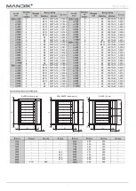
Страница 8: ...0TA 12 0 2584 7 BF 360TA 12 0 4735 4 BF 360TA 12 0 3066 7 BF 360TA 12 0 5167 4 BF 360TA 12 0 3258 8 BF 360TA 20 0 5253 5 BF 360TA 12 0 3644 8 BF 360TA 20 0 5685 5 BF 360TA 12 0 3933 2 BFN 340TA 05 0 1536 5 BF 360TA 12 0 4126 2 BFN 340TA 05 0 1581 6 BF 360TA 12 0 4222 3 BFN 360TA 12 0 1947 6 BF 360TA 12 0 4319 3 BFN 360TA 12 0 2358 6 BF 360TA 12 0 4704 4 BFN 360TA 12 0 2450 6 BF 360TA 12 0 4897 4 B...

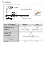
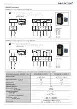
Страница 9: ...tage not permitted at the both auxiliary switches Application examples for integration into monitoring and control systems or into bus networks can be found in the documentation of the connected communication and power supply unit 1 blue 2 brown S1 violet S2 red S3 white S4 orange S5 pink S6 grey AC 230 V 50 60 Hz AC 24 V 50 60 Hz DC 24 V motoring holding 3 5 5 W 1 1 2 1 W 2 5 4 W 0 8 1 4 W 6 5 10...

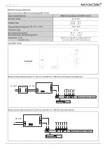
Страница 10: ...mum distance between contacts 3 mm to network and communication device BKN230 24 BAE72B S Tf1 Tf2 Tf3 LED 230V 50 60 Hz 24V AC DC 50 60 Hz motoring holding 7 W 2 W 8 W 3 W 10 VA Imax 8 3 A 5 ms 12 5 VA Imax 500 mA 5 ms III II IP 54 motor spring return 140 s 16 s normal duty safety duty non operating temperature 20 C 50 C The safe position will be attained up to max 75 C 40 C 50 C motor auxiliary s...

Страница 11: ...ite WH4 white WH5 white WH6 white Attention Mains voltage Servo must be protected by breaker max 16 A Parallel connection of other servo drives is possible Respect power input data Combination of mains voltage and use of signals from limit switches by very low voltage is not allowed 1 2 TA 72 TF1 TF2 LED test 80 5 1 2 3 4 5 6 S1 S2 WH WH WH WH WH WH BU BN Connect through separating transformer Par...

Страница 12: ... 11 5 VA 7 VA II III IP 54 motor spring return 75 s 20 s normal duty safety duty non operating temperature 30 C 50 C 75 C 30 C 50 C motor auxiliary switch cable 1 m 2 x 0 75 mm cable 1 m 6 x 0 75 mm TF1 temperature inside Duct 72 C TF2 temperature outside Duct 71 C 230V 50 60 Hz 24V AC DC 50 60 Hz motoring holding 10 5 W 2 5 W 10 5 W 2 5 W 22 5 VA 14 VA II III IP 54 motor spring return 75 s 20 s n...

Страница 13: ...18 28 V DC 24 30 V without servo drive max 50mA IP 30 25 C 70 C 5 C 40 C mains drive BF Top cable 1m connected to terminal board XT1 screw terminals in XT2 terminal board AC 24V AC 230V L1 N ZNP 10 24V 230V 24V AC 24V ...

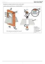
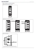
Страница 14: ...ansfer of load effects from any walls structures and other parts onto damper frame are excluded completely During walling in the damper frame must not be deformed After having been built in the damper its blades must not rub on damper frame or one another When dampers are installed in walls they must be built in in such a way so that the damper side with thermo electric actuator mates with the wal...

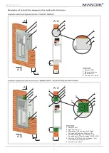
Страница 15: ...A A A A 100 100 50 Damper FDML Rigid wall structure Mineral wool with min density 140kg m for instance Rockwool Steprock HD Fire stop SEALANT min thickness 1 mm for instance HILTI Acrylic sealant CFS S ACR Fire stop COATING min thickness 1 mm HILTI Firestop coating CFS CT Fire stop cover plates ...

Страница 16: ...for instance Rockwool Steprock HD Fire stop SEALANT min thickness 1 mm for instance HILTI Acrylic sealant CFS S ACR Fire stop COATING min thickness 1 mm HILTI Firestop coating CFS CT Fire stop cover plates A A A A 100 100 Damper FDML Plasterboard wall structure Plaster mortar Fire stop cover plates 50 ...

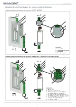
Страница 17: ...16 Damper FDML Rigid wall structure Plaster mortar Fire stop cover plates Covered mechanism Covered sensor Duct 100 100 A A A A 50 ...

Страница 18: ...17 150 150 150 150 Frame into the wall Duct Covering grill Before walling in the damper casing must be grounded Earth connection screw ...

Страница 19: ...al qualification with validity 5 years and its prolongation must be provided by AUTHORIZED PERSON itself directly at trainer premises When terminates validity of the CERTIFICATE such CERTIFICATE becomes void and it is discarded from trainer files Only qualified persons can be trained who then answer for performed works Damper must be installed with respecting of all safety standards and regulation...

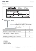
Страница 20: ...V AC DC with thermo electric actuator 50 with servo drive Belimo or Gruner 24V AC DC with optical smoke detector MHG 231 assembly voltage 24V AC 51 Optical smoke detectors MHG 231 and supply unit BKN 230 24 MP are in bulk 2 grills included damper is inside wall protected from both sites with grills there is no connection with air ductwork without grills damper is part and connected to the air duct...

Отзывы: