Mandik FDML Скачать руководство пользователя страница 16

Fire damper - FDML

Page 16

Version 2023-10-31

TPM 130/17

The damper can be installed with blade axis vertically or
horizontally, temperature sensor (BAT) must always be in
damper  upper  part.  The  damper  installation  procedures
must  be  done  so  that  all  load  transfer  from  the  fire
separating  constructions  to  the  damper  is  absolutely
excluded.  Following  air-conditioning  duct  must  be
suspended or supported so that all load transfer from the
following duct to the fire damper is absolutely excluded.
The  gap  between  the  installed  damper  and  the  fire
separating  construction  must  be  perfectly  filled  with
approved material.

During  the  installation  and  plastering  process,  the
actuating  mechanism  must  be  protected  (covered)
against damage and pollution. The damper casing should
not be deformed during bricking in. Once the damper is
built in, the damper blades should not grind against the
damper casing during opening or closing.

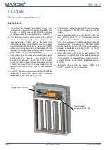
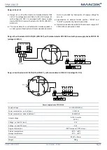
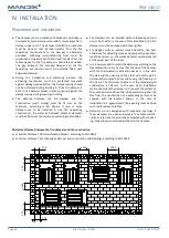
The  distance  between  the  fire  damper  and  the
construction  (wall,  ceiling)  must  be  75  mm  at  the
minimum,  according  to  EN  1366-2.  If  two  or  more
dampers  are  to  be  installed  in  one  fire  separating
construction,  the  distance  between  adjacent  dampers
must be 200 mm at the minimum, according to EN 1366-2.

Fire dampers can be installed without following duct on
one or both sides. In the case of this installation, the fire
dampers must be equipped with cover grilles.

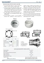
For  designs  with  an  optical  smoke  detector,  the  best
conditions for detecting smoke and combustion products
must be ensured, i.e. the smoke detector must be located
at the upper part of the room.

It is recommended to install the dampers according to the
local disposition in such a way that the side of the damper
with  the  thermoelectric  activation  device  is  in  line  with
the wall and the opening on the other side of the wall is
permanently covered by a second cover grille fixed e.g. in
the  frame.  The  minimum  thickness  of  the  standard  wall
construction  is  100  mm.  In  the  case  of  an  installation
where one side of the damper is in line with the surface of
the construction and the other side extends more than 25
mm  from  the  construction,  the  extending  part  must  be
covered  with  fire-resistant  boards.  In  the  case  of
installation in a gypsum wall, the opening must be lined
with reinforcement profiles.

Dampers  are  not  equipped  with  inspection  openings.  If
these  dampers  are  used  as  dampers  for  simple  mainte-
nance and revision they must be completed with connect-
ing inspection part installed just behind the damper.

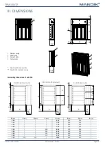
Minimum distance between the fire dampers and the construction

minimum distance 200 mm between dampers, according to EN 1366-2

minimum distance 75 mm between damper and construction (wall/ceiling), according to EN 1366-2

IV. INSTALLATION

Placement and installation

 75

 75

 7

5

 2

0

0

 7

5

 200

 200

Содержание FDML

Страница 1: ...stomice esk republika Tel 420 311 706 742 E Mail mandik mandik cz www mandik com FDML Multi blade fire damper Technical Documentation Installation Commissioning Operation Maintenance and Service Manua...

Страница 2: ...rs 12 IV INSTALLATION 16 Placement and installation 16 Statement of installations 17 In solid wall construction 18 In gypsum wall construction 20 In solid ceiling construction 22 Examples of installat...

Страница 3: ...fire dampers are in motorised design only with actuator and they have the following two main applications For use as a fire shutter without following air duct with cover grilles for closing ventilatio...

Страница 4: ...N to the position CLOSED takes maximum 20 sec In case that the power supply is restored again the blades can be in any position the actuator starts to rotate the damper blades back to the position OPE...

Страница 5: ...A 5 ms Protection class II III Degree of protection IP 54 Running time motor spring return 60 s 20 s Ambient temperature normal duty safety duty non operating temperature 30 C 55 C The safe position w...

Страница 6: ...egree of protection IP 54 Running time motor spring return 60 s 20 s Ambient temperature normal duty safety duty non operating temperature 30 C 55 C The safe position will be attained up to max 75 C 4...

Страница 7: ...otection IP 54 Running time motor spring return 120 s 16 s Ambient temperature normal duty safety duty non operating temperature 30 C 50 C The safe position will be attained up to max 75 C 40 C 50 C C...

Страница 8: ...1 is interrupted due to temperature outside the duct it is necessary to replace the spring return actuator Thermoelectric activation device BAT is integral part of the actuator If the thermal fuse Tf2...

Страница 9: ...e delivered in bulk Design 41 and 51 Design 41 with actuator BF 24 TN BFL BFN 24 T with smoke detector ORS 142 K and with power supply device ZNP 10 24 voltage AC 230 V Power supply device ZNP 10 24 S...

Страница 10: ...d stays in this state even if the smoke disappears from the scanning chamber The sensor remains in the alarm state until the power supply is briefly reset On the pin 3 an external device can be connec...

Страница 11: ...h of a damper casing Connecting dimensions of nuts M6 B 400 without nuts 400 B 600 one nut B 600 two nuts B mm R mm Q mm S mm B mm R mm Q mm S mm 300 650 220 230 315 700 240 245 355 710 240 250 400 75...

Страница 12: ...0748 500 4 24 2 1 5 0 0681 500 4 25 9 1 7 0 0887 560 4 26 5 1 7 0 0723 560 4 28 5 1 8 0 0943 600 5 27 7 1 7 0 0809 600 5 29 7 2 3 0 1055 630 5 29 0 1 8 0 0873 630 5 31 1 2 3 0 1138 650 5 29 7 1 8 0 0...

Страница 13: ...500 4 29 8 2 4 0 1317 500 4 33 8 2 7 0 1794 560 4 33 0 2 5 0 1399 560 4 37 6 2 9 0 1906 600 5 34 2 2 6 0 1565 600 5 38 9 3 1 0 2132 630 5 35 8 2 7 0 1689 630 5 40 7 3 1 0 2301 650 5 36 6 2 8 0 1772 6...

Страница 14: ...48 500 4 36 5 3 0 0 2112 500 4 39 2 3 2 0 2430 560 4 40 6 3 2 0 2244 560 4 43 7 3 5 0 2582 600 5 42 0 3 3 0 2510 600 5 46 8 3 6 0 2888 BF 630 5 43 9 3 4 0 2709 630 5 48 8 3 7 0 3117 650 5 44 9 3 5 0 2...

Страница 15: ...30 8 2 9 0 1620 BFN 700 6 56 7 4 3 0 3784 315 2 32 2 3 0 0 1668 710 6 57 4 4 3 0 3871 355 3 33 8 3 1 0 2053 750 6 60 2 4 5 0 4216 400 3 37 1 3 3 0 2487 800 6 64 1 4 6 0 4389 450 4 42 6 3 5 0 2584 BF...

Страница 16: ...s In the case of this installation the fire dampers must be equipped with cover grilles For designs with an optical smoke detector the best conditions for detecting smoke and combustion products must...

Страница 17: ...re resistance Page In solid wall construction 100 Mortar or gypsum EI 90 ve i o S 18 Weichschott system 19 In gypsum wall construction Mortar or gypsum 20 Weichschott system 21 In solid ceiling constr...

Страница 18: ...y if one side of the damper is in line with the surface of the construction and the other side extends more than 25 mm from the construction Promatect H min thickness 15 mm connect the boards together...

Страница 19: ...only if one side of the damper is in line with the surface of the construction and the other side extends more than 25 mm from the construction Promatect H min thickness 15 mm connect the boards toget...

Страница 20: ...ly if one side of the damper is in line with the surface of the construction and the other side extends more than 25 mm from the construction Promatect H min thickness 15 mm connect the boards togethe...

Страница 21: ...only if one side of the damper is in line with the surface of the construction and the other side extends more than 25 mm from the construction Promatect H min thickness 15 mm connect the boards toget...

Страница 22: ...ML 2 Solid ceiling construction 3 Mortar or gypsum B min B 100 max B 300 A 190 min A 290 max A 490 150 50 150 X 50 150 X 15 0 In case with connected duct and with forced air flow In case without conne...

Страница 23: ...ith the wall fire resistant cover boards required Damper in th centre of the wall fire resistant cover boards not required Damper in the wall 150 mm Damper with grille on the wall Damper with duct and...

Страница 24: ...t M8 with anchor Solid wall construction or Screw with hexagon head Gypsum wall construction 6 Bolt M6x20 large area washer Examples of fixing FDML B 30 15 2x 13 2x 8 4 min 30 min 30 Screw two L profi...

Страница 25: ...profile overlap 30 mm on each side L profile is not part of the delivery 5 Nut M8 with anchor 6 Bolt M6x20 large area washer min 3 Screw two L profiles to the damper using M6x20 screws washers and fi...

Страница 26: ...les for rivets in the damper flange and rivet the damper holders There must be at least 2 holders on each side of the damper with a maximum spacing of 200 mm and a maximum distance from the edge of th...

Страница 27: ...L 2 Duct 3 Damping pad 4 Steel clamp min screw M8 5 Screws M6 in corners more about connecting dimensions see page 11 6 Self drilling screw connection of the flanges of the damper and the duct 7 Seali...

Страница 28: ...TA Pressure loss Pressure loss calculation Determination of pressure loss by using diagram 1 2 kg m3 p w2 2 p Pa presure loss w m s air flow speed in nominal damper section kg m3 air density coefficie...

Страница 29: ...2 538 2 491 2 459 2 436 2 373 2 302 2 223 2 145 2 050 Coefficient of local pressure loss A B 600 630 650 700 710 750 800 850 900 950 1000 300 3 261 3 192 3 146 3 031 3 007 2 915 2 800 2 684 2 569 2 45...

Страница 30: ...ts Cover grilles are always made of common steel sheet metal with a burning varnish The damper blades in the variant for chemical environments Class A4 are always treated with a coating of chemically...

Страница 31: ...ct ing inspection part installed just behind the damper Installation fixing the damper Assembly maintenance and damper function check can be done only by qualified and trained person i e AUTHORIZED PE...

Страница 32: ...de periodical checks maintenance and service actions on fire equipment by authorized persons The authorized persons can be trained by producer or by authorized distributor All effective safety standar...

Страница 33: ...K and with supply device ZNP 10 24 voltage 230 V AC 41 With actuator BF 24 TN BFL BFN 24 T voltage AC DC 24 V 50 With actuator BF 24 TN BFL BFN 24 T with smoke detector ORS 142 K voltage 24V DC 51 Dat...

Страница 34: ...om The producer reserves the right for innovations of the product For actual product information see www mandik com MAND K a s Dob sk 550 267 24 Hostomice esk republika Tel 420 311 706 742 E Mail mand...

Отзывы: