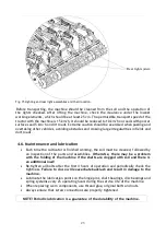
Mandam TOP 2.5 Скачать руководство пользователя страница 26

26 

Post-season service


      After the working season, the cultivator should be thoroughly cleaned, the damage to 
the varnish coating should be repaired, and the stripped working surfaces of the teeth, 
discs, strings and roller rings, as well as the threads of the adjusting screws, should be 
washed with "Antykor" paraffin and protected against corrosion with "Antykor 1" grease, 
and a full lubrication should be carried out. It is advisable to store the machine under a 
canopy when not in use. However, if this is not possible, the condition of the protection 
should be checked from time to time and, if necessary, the rain-washed grease should be 
replenished.


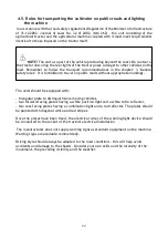
The cultivator should be stored in a place that poses no danger to persons 

or the environment

. The machine, when uncoupled from the tractor, should be supported 

on firm and level ground. Also, components dismantled from the machine should be stored 
securely supported on the ground, excluding possible uncontrolled movement.


Clean the piston rods of the hydraulic cylinders during winter and when the machine 
is not in use for a long period of time, and protect them with vaseline or acid-free 
grease to protect them from corrosion.
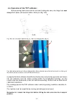


 5.1.


Operation of the hydraulic system


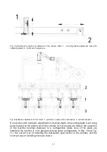
Maintenance  of  the  hydraulic  system  (Fig.  17,  18,  19,  20)  consists  of  a  visual 

inspection for leaks. Remember to put plugs on the quick-release couplings. Oil leakage 
at the connections of the hydraulic lines should be tightened. If this does not rectify the 
fault, the component or hose must be replaced with a new one.  Leakage occurring outside 
the connector - the leaking hose must be replaced with a new one. Mechanical damage 
also requires replacement of the component. It is recommended to replace the hydraulic 
hoses every 5 years.


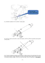
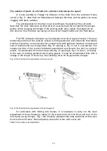
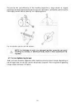
The appearance of oil on the piston rod of a hydraulic cylinder should be checked 

for the nature of the leak. When the piston rod is fully extended, check the sealing points. 
Minor leaks characterised by wetting of the piston rod with an "oil film" are permissible 
(defective sealing ring). In the event of heavier sweating or the appearance of drops, the 
unit should be switched off while the fault is being rectified (defective seal).


Содержание TOP 2.5

Страница 1: ...z o o 44 100 Gliwice ul Toru ska 14 e mail mandam mandam com pl Phone 48 32 232 26 60 Fax 032 232 58 85 TIN 648 000 16 74 REGON statistical No P 008173131 OPERATION MANUAL TOP cultivator Revision III...

Страница 2: ...ws No 199 item 1228 and Directiveof the European Union 2006 42 EC of 17 May 2006 Persons responsible for the technical documentation of the machine Jaros aw Kudlek ukasz Jakus ul Toru ska 14 44 100 Gl...

Страница 3: ...isk 11 4 General information on use 12 4 1 Preparing the cultivator for work 14 4 2 Coupling the cultivator to the tractor 16 4 3 Operation and adjustment 16 4 4 Operation of the TOP cultivator 21 4 5...

Страница 4: ...provisions of this manual please contact the manufacturer Notes that are important for safety reasons are marked with the sign The machine has a data plate located on the main frame The plate contains...

Страница 5: ...ns that are lost or illegible should be replaced with new ones Table 1 Information and warning signs Safety signs Meaning of the safety sign Location on the machine Read the operating instructions bef...

Страница 6: ...f parts may move Mid frame near side frames Pressurised liquid jet bodily harm Cylinders Fixing point for transport belts Upper part of the drawbar upper fastener bolt Rear frame part rigid frame adja...

Страница 7: ...Frame 2 right side frame 3 left side frame 4 disc beam 5 shaft 6 shaft arm 7 drawbar 8 working component 9 shaft bracket 10 right disc 11 left disc 12 cylinder 13 hydraulics mechanical lock 14 bumper...

Страница 8: ...vator transport carriage 1 axle with wheels 2 carriage frame 3 cylinder with hydraulic system fig 13 4 frame holder 5 turnbuckle 6 drawbar Table 2 Technical data of the TOP cultivator Type Working wid...

Страница 9: ...need of ploughing and as such this allows cost reduction eliminates the risk of excessively compacted soil and helps to complete farming work on time NOTE The cultivator is designed exclusively for a...

Страница 10: ...nd to secure the suspension pins with split pins When coupling the tractor to the cultivator it is forbidden for persons to stay between the machine and the tractor during this time The tractor workin...

Страница 11: ...nsion system and there are no excessive loads on the machine frame and the tractor s suspension system Particular care should be taken when passing and overtaking and on bends The permissible width of...

Страница 12: ...to the transport position The plough beams with working components are attached to the frame Standard cultivators are equipped with a shaft and a disc beam mounted to the shaft arms The task of the di...

Страница 13: ...nt mounted device a distance between the centre of gravity of the front mounted device and the centre of the axle b tractor wheel track c distance between the centre of the rear axle and the centre of...

Страница 14: ...hine make sure there are no bystanders in the vicinity 4 1 Preparing the cultivator for work The cultivator is usually delivered ready for work Due to the limitations of transport facilities it is als...

Страница 15: ...afts in the arm holders requires that the bolts be evenly tightened diagonally so that the entire plane of the arm holders is adjacent to the plane of the shaft clamp profile This provides the most se...

Страница 16: ...ooks drive up carefully suspend the machine from the lower links then secure connect the top upper fastener on the tractor During operation of the unit the hitch point of the upper fastener at the uni...

Страница 17: ...th hydraulic adjustment of working depth the working depth is set using pawls located at the piston rod of the cylinder As more pawls are folded the operation of the machine becomes shallower In a con...

Страница 18: ...the machine Fig 11 Incorrect installation of pawls on cylinder piston rod Partial omission of the attachment of the pawls to the cylinder results in uneven distribution of the forces acting on the pis...

Страница 19: ...e stubble with low loosening recommended for compact soils with optimum moisture content and soils of medium and low compactness Fig 12 opening A Fig 13 nut C unscrewed The steeper position of the cou...

Страница 20: ...member to remove the hinge lock before lifting the side arms into the transport position A properly hitched cultivator should follow the tractor evenly during operation and loosen the soil uniformly o...

Страница 21: ...turn to lock with the mid frame 1 A properly hitched cultivator should follow the tractor evenly during operation and loosen the soil uniformly over the entire working width For longitudinal levelling...

Страница 22: ...diagonal white and red stripes Once the plates have been fixed the electrical wires of the warning light device should be connected to the socket of the tractor s electrical installation The manufact...

Страница 23: ...cation Each time the cultivator is finished working the soil must be cleaned followed by an inspection of the parts and assemblies Otherwise there may be a problem with the folding of the machine if t...

Страница 24: ...g 16 Lubrication points on the TOP cultivator NOTE It is forbidden to work on a damaged machine caused by any event resulting in a broken or deformed frame shaft or other assembly of the machine 4 7 S...

Страница 25: ...plant debris each time after use and inspect the bolt and pin connections and the condition of the working elements and other parts When cleaning plant debris and strings winding up at the bearing poi...

Страница 26: ...ods of the hydraulic cylinders during winter and when the machine is not in use for a long period of time and protect them with vaseline or acid free grease to protect them from corrosion 5 1 Operatio...

Страница 27: ...2 quick coupling 3 T piece 4 orifice 5 copper washer 6 hydraulic hose 1m 7 hydraulic hose 0 7m 8 hydraulic hose 2 2m Fig 18 Diagram of the hydraulic system of the TOP carriage 1 cylinder 2 3 hydrauli...

Страница 28: ...Next take the wheel to a specialised workshop to locate and repair the damage Significantly damaged tyres particularly profile damage must be replaced immediately Setting of wheel bearing axial cleara...

Страница 29: ...r before winter the drainage valve should be unscrewed and cleaned Checking the pneumatic system involves visually inspecting for leaks especially at the connection points when checking the system the...

Страница 30: ...nect the cylinder to the system and when mounted on one side run through the entire cycle a couple of times to fill the cylinder completely with oil Failure to do so may result in a sudden fall of the...

Страница 31: ...ANDAM machines please visit our website at www mandam com pl tab Parts On this page we provide catalogues and spare parts sheets in PDF format containing up to date parts diagrams for each machine tog...

Отзывы: