


Commissioning and operation
40
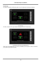
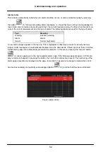
Alarms
Definition of alarm condition
An alarm is triggered when a monitored value exceeds or fails to reach its set limit value.
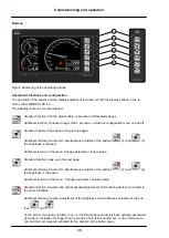
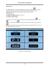
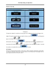
Should an alarm condition occur, an alarm table is automatically displayed. This lists all advance warnings,
alarms and sensor fault alarms. An internal buzzer and the horn relay are activated at the same time.
The collective alarm relay issues a repeat pulse if another alarm was already active. In this way, it is pos
sible to activate a visual call system for each new alarm or to send a telephone message if the ship is not
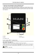
occupied. Acoustic acknowledgement with the
(4) button switches the internal buzzer off and the
horn relay drops out.
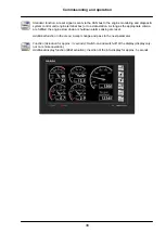
Alarm acknowledgements and reset signals are sent on the CAN bus to the engine monitoring and dia
gnostic system Diagnostics unit and to all the monitoring devices subscribing to the same CAN bus. All the
equipment thus has the same alarm status.
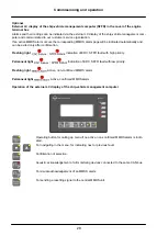
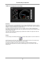
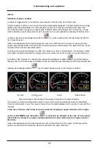
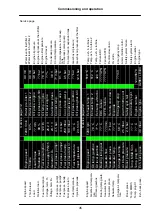
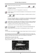
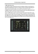
So long as the values are displayed in white, the values are in their “normal ranges". On reaching a prelim
inary alarm the digital value flashes orange, with a main alarm red, and in the case of a sensor fault a yel
low flashing “SE" appears. On pressing the optical acknowledgement (Button
(4)) all the flashing
displays revert to a continuously lit condition. When the fault has been eliminated and both acoustically and
optically acknowledged (button
(4)), the alarm display reverts to the “Normal condition".
Normal
Advance war
ning
Alarm
Sensor failure
Figure: Example of the display of the engine oil pressure with alarm indication
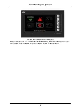
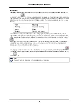
The engine monitoring and diagnostic system control unit monitors all important sensors for plausibility.
If a sensor fault alarm occurs, the value is cleared from the digital displays and the pointer is removed from
the dials.
In the case of alarms, which have led to the automatic stopping or speed reduction of the engine
via the central MMDS unit, the button
(5)
must also be actuated. In the case of a stop alarm,
this function is released on engine shutdown and with a reduce alarm below an engine speed of
800 1/min.
Alarm acknowledgements and reset signals are sent via the CAN bus to the engine monitoring and dia
gnostic unit and to all the monitoring devices connected to the same CAN bus.
Содержание D2862 LE423
Страница 6: ...Declaration 6...
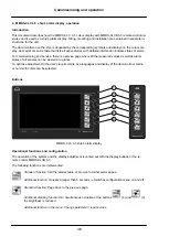
Страница 14: ...Commissioning and operation 14 Engine views V8 1200 D2868 LE433 2 3 4 5 6 7 8 9 1 10 11 10 12 3 8...
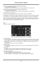
Страница 42: ...Commissioning and operation 42 Active alarm page Figure Alarms table Acknowledged alarm page...
Страница 131: ......
Страница 132: ...MAN Truck Bus AG Vogelweiherstra e 33 90441 N rnberg Germany A member of the MAN Group Printed in Germany 51 99493 8578...


