5
6
7
8
Removing and Installing Injection Pump
30
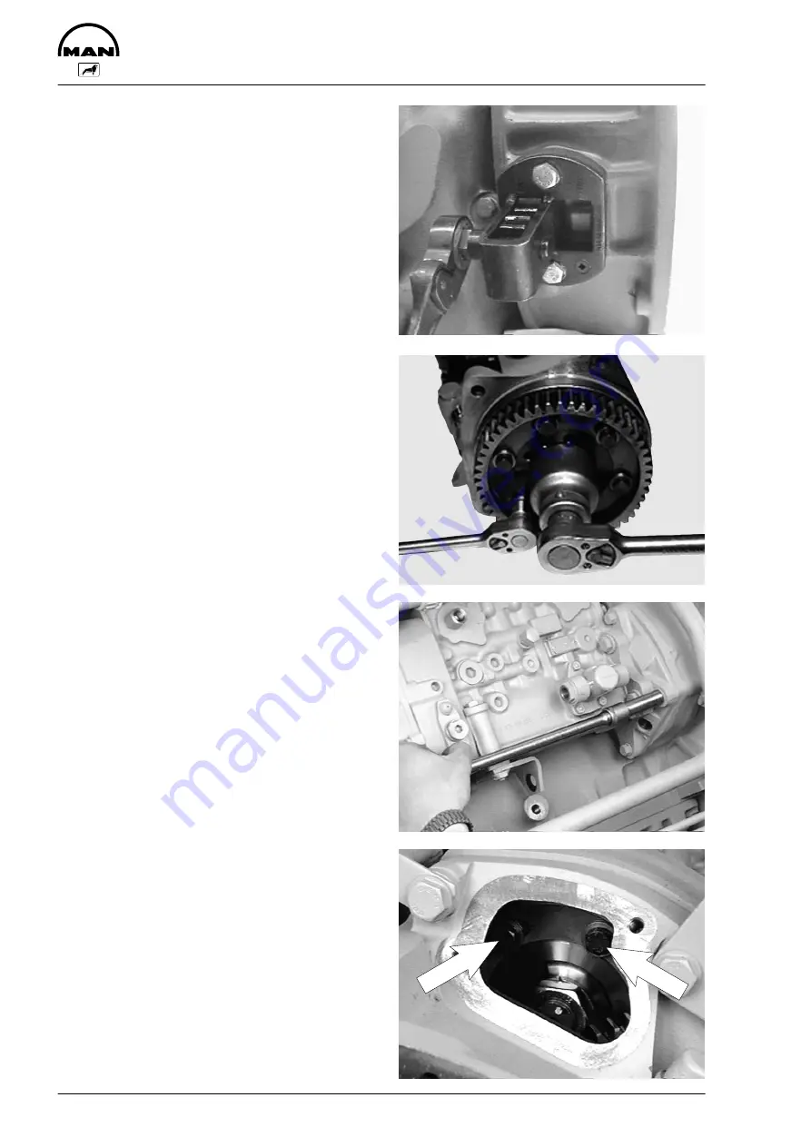
Fig. 5
Turn engine to angle for delivery start.
Remove the cylinder head cover from cylinder no.
6 (flywheel end).
When the valves for this cylinder overlap, the
piston in cylinder no. 1 is at firing TDC.
Fig. 6
Check whether the injection pump is at start of de-
livery. Remove screw plug on governor housing
(see Fig. 4). The start-of-delivery pointer must be
visible in the centre of the inspection hole.
Remove the mounting bolts from the injection
pump drive gear so that it can be turned in the
slots.
Hold the injection pump camshaft in place while
turning the gear.
Fit a new O-ring (lightly oiled) on the injection
pump flange.
Fig. 7
Insert the injection pump and tighten the mounting
bolts to specified torque.
Fig. 8
Provisionally tighten all the mounting bolts of the
gear through the inspection hole to 5 Nm. Two
complete engine revolutions are necessary for this.
Now tighten down all the mounting bolts to 30 Nm.
Check and if necessary set start of delivery (see
Page 28).
Screw in screw plug on the governor housing and
fit cover to timing case.
Содержание D 2866 LUE 605
Страница 1: ......
Страница 2: ......
Страница 14: ...Notes 12...
Страница 19: ...Memoranda 17...
Страница 20: ...Engine views 18 Engine views 3 4 2 1 7 6 5 8 11 10 9...
Страница 68: ...Memoranda 66...
Страница 133: ...131 Service Data...
Страница 157: ...155 Special tools...
Страница 158: ...Special tools 156 2 3 4 5 6 7 8 1 6 1 6 2 6 3 9 1 9 2 9 3 9...
Страница 160: ...Special tools 158 10 11 16 14 14 1 12 13 18 18 1 12 1 12 2 15 5 15 4 15 1 15 1 15 2 15 3 15 3 15 6 15 7 15 17...
Страница 162: ...Special tools 160 21 22 25 25 2 24 25 1 26 27 1 27 2 27 20 1 19 2 19 1 20 2 19 20 23 28...
Страница 164: ...Special tools 162 30 31 32 1 32 32 2...
Страница 167: ...Special tools 165 Pressing mandel for cap dia 62 1 mm Pressing mandel for cap dia 50 1 mm...
Страница 170: ...Notes 168...
Страница 173: ......
Страница 174: ......


