Condensing Boiler
21
6/03/00
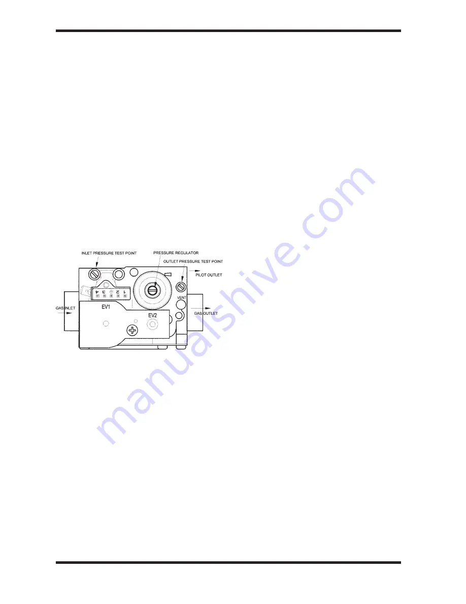
2. Gas Valve
•
Lower the Electrical Tray.
•
Turn the Gas Cock off.
•
Pull off the electrical connector from the
Gas Valve.
•
Release the pilot feed tube.
•
Undo the four shoulder bolts at each end of
the valve.
TAKE CARE TO SUPPORT THE VALVE
AS IT IS RELEASED.
•
Replacement is the reverse.
•
When secure, attach a manometer to the
burner pressure tapping on the right hand
side of the valve.
•
The Pilot Adjuster is factory set.
•
Turn on gas and electrical supply.
•
The gas valve slowly opens to its setting
ensure it has fully opened before adjusting.
•
Set burner gas pressure with the governor.
(see Technical Data on page 1 for figure)
Removing the Case
•
Lower the Electrical Tray.
•
Undo the two M5 screws at the base of the
Case.
•
Lift the Case straight up about half an inch
(12mm).
•
Gently pull the Case straight forward off the
hidden studs at the top of the boiler. (The
cover hangs on two studs in keyhole slots)
•
Examine the sealing strip for damage and
replace if necessary.
•
Place the Case somewhere safe from
damage
IMPORTANT: FAILURE TO CORRECTLY
LOCATE THE APPLIANCE CASE COULD
RESULT IN LEAKAGE OF COMBUSTION
PRODUCTS INTO THE ROOM.
3. Fan Assembly
•
Lower the Electrical Tray.
•
Remove the Case.
•
Undo the wing nut holding the Fan Protec-
tion Hoop.
•
Pull the electrical connectors off the Fan.
•
Gently pull the pressure tubing off the
tappings on the Flue Hood.
•
Undo the two screws holding the Flue Hood
and slide forward and away.
•
Re-assembly is the reverse.
4. Air Pressure Switch
•
Lower the Electrical Tray.
•
Remove the Case.
•
Pull the electrical connectors off the Air
Pressure Switch.
•
Gently pull the pressure tubing off the both
tappings on the switch.
•
Undo the M4 nut and wing nut holding the
Air Pressure Switch to its bracket on to the
Back Panel
•
Lift off its studs and rotate out of its bracket.
•
Re-assembly is the reverse.
5. Flue Thermostat
•
Lower the Electrical Tray.
•
Remove the Case.
•
Pull the electrical connectors off the Flue
Thermostat.
•
Re-assembly is the reverse.
6. Control Sensor
•
Lower the Electrical Tray.
•
Remove the Case.
•
Unclip the sensor.
•
Pull the electrical connectors off the Control
sensor.
•
Re-assembly is the reverse.
7. Overheat Cut-off Device
•
Lower the Electrical Tray.
•
Remove the Case.
•
Pull the electrical connectors off the Over-
heat Cut-off device.
•
Unscrew from its mounting.
•
Re-assembly is the reverse.
•
Lower the Electrical Tray.


