background image

27

IT

ALIANO

ENGLISH

FRANÇ

AIS

DEUT

SCH

Fig. 1

Содержание CDI

Страница 1: ...1 ITALIANO ENGLISH FRANÇAIS DEUTSCH Centraline elettroniche ...

Страница 2: ...2 ITALIANO ENGLISH FRANÇAIS DEUTSCH ...

Страница 3: ...e Inserire il connettore proveniente dalla centralina Malossi Riconnettere al bypass il connettore originale per chiudere il circuito Fig 4 part C Individuare il connettore diagnosi veicolo Fig 5 posizionato come indicato in Fig 6 A B C Togliere il tappo di protezione al connettore originale e inserire il connettore Malossi Fig 8 Fissare la centralina Taratura TPS throttle position sensor Fig 8 Ru...

Страница 4: ... telaio 3 Centralina danneggiata ARANCIONE indica l avvenuta variazione della regolazione dei trimmer VERDE il led verde acceso indica il corretto funzionamento della centralina Se a chiave ON il led verde non si illumina significa che la centralina non riceve corrente Per risolvere il problema procedere con la verifica dei cablaggi per controllare che questi siano stati eseguiti correttamente Fun...

Страница 5: ...DB killer Curva 3 valori di regolazione azzerati Art 5515724 4 diverse mappature Curva 0 cilindro originale testa originale scarico Malossi con DB killer Curva 1 cilindro originale testa Malossi scarico Malossi con DB killer Curva 2 cilindro Malossi testa Malossi scarico originale Curva 3 cilindro Malossi testa Malossi scarico Malossi con DB killer Art 5516089 4 diverse mappature Curva 0 Cilindro ...

Страница 6: ...ato sul segno si ha una regolazione di 20 Con il potenziometro posizionato sul segno si ha una regolazione di 20 Regolando il potenziometro tra questi due punti si aggiungerà o sottrarrà una quantità di carburante proporzionale a quanto la tacca viene spostata dallo zero Regolazione Per selezionare la curva adatta cominciare verificando che tutti e tre i potenziometri siano posizionati sullo zero ...

Страница 7: ...che il connettore femmina dell emulatore deve essere connesso al connettore maschio della Force Master Infine collegare il connettore femmina della Force Master all iniettore Speriamo che lei abbia trovato sufficientemente esaustive le indicazioni che precedono Nel caso in cui qualche punto le risultasse poco chiaro potrà interpellarci per iscritto compilando l apposito modulo inserito nella sezio...

Страница 8: ...e di stampa La presente pubblicazione sostituisce ed annulla tutte le precedenti riferite agli aggiornamenti trattati Garanzia Consulta le condizioni relative alla garanzia sul nostro sito malossistore com Prodotti riservati esclusivamente alle competizioni nei luoghi ad esse destinate secondo le disposizioni delle competenti autorità sportive Decliniamo ogni responsabilità per l uso improprio ...

Страница 9: ...nector to the ECU s bypass to complete the circuit Fig 4 part C Locate the diagnosis connector of the vehicle Fig 5 positioned as indicated in Fig 6 A B C Remove the protection tap from the original connector and put in the Malossi connector Fig 8 Fix the CDI TPS Throttle Position Sensor Calibration Fig 8 Rotate the LOW trimmer to the red arrow position Turn the ignition key to the ON position Wai...

Страница 10: ...justed correctly GREEN indicates the ECU is functioning correctly if the green LED does not illuminate when the ignition is switched on then this indicates no power to the ECU Make sure that you have properly connected the wiring harness Working The Force Master 2 CDI is preprogrammed with 4 base fuel curves The curves are selected using the switch labeled MAPS These curves adjust fuel delivery ba...

Страница 11: ...l cylinder original head Malossi exhaust system with DB killer Curve 1 original cylinder Malossi head Malossi exhaust system with DB killer Curve 2 Malossi cylinder Malossi head original exhaust system Curve 3 Malossi cylinder Malossi head Malossi exhaust system with DB killer Art 5516089 4 different maps Curve 0 Malossi cylinder Original exhaust system Original camshaft Original head Curve 1 Malo...

Страница 12: ...h the potentiometer pointed straight up at the mark is 20 With the potentiometer pointed straight up at the mark is 20 Adjusting the potentiometer between these points will result in adding or subtracting an amount of fuel proportional to how far the knob was moved from zero Calibration To select the right curve start by making sure that all 3 of the RPM pots are set to zero adjustment Then select...

Страница 13: ...e connected to the male connector of the Force Master In the end the female connector of the Force Master must be connected to the injector We hope you found the above instructions sufficiently clear However if any points are not particularly clear please contact us completing the special form inserted in the contact section on our Internet site malossistore com We thank you in advance for any com...

Страница 14: ...ook up warranty terms in our website malossistore com These products are reserved solely for races in locations reserved for those purposes and in accordance with the regulations issued by the competent authorities for sports events We decline any and all responsibility for improper use ...

Страница 15: ...nnecteur Insérez le connecteur en provenance du boîtier électronique Malossi Connectez le connecteur d origine au bypass pour fermer le circuit Fig 4 part C Localiser le connecteur diagnostic du véhicule Fig 5 positionné comme indiqué dans la figure 4 Enlever du connecteur d origine le bouchon de protection et insérer le connecteur Malossi i Fig 8 Fixez le boîtier Réglage TPS Throttle position sen...

Страница 16: ...e partie du cadre 3 Boîtier CDI endommagé ORANGE indique la variation du réglagle du trimmer VERT a led vert allumé indique le correct fonctionnement du boîtier Si avec la clé ON la led verte ne s éclaire pas le boîtier ne reçoit pas le courant Pour résoudre le problème il faut vérifier les câblages pour contrôler qu ils soient corrects Fonctionnement Le boîtier éléctronique Force Master 2 est pro...

Страница 17: ...indre d origine culasse d origine pot d échappement Malossi avec DB killer Courbe 1 cylindre d origine culasse Malossi pot d échappement Malossi avec DB killer Courbe 2 cylindre Malossi culasse Malossi pot d échappement d origine Courbe 3 cylindre Malossi culasse Malossi pot d échappement Malossi avec DB killer Art 5516089 4 programmes differents Courbe 0 Cylindre Malossi Pot d échappement d origi...

Страница 18: ...ce on a une régulation de 20 Avec le potentiomètre positionné sur l enchoce on a une régulation de 20 En réglant le potentiomètre entre ces deux positions vous pouvez ajouter ou enlever une quantité de carburant proportionelle au déplacement de l enchoce du zero Régulation Pour sélectionner la courbe appropriée il faut commencer en vérifiant que les 3 potentiomètres soient positonnés à zéro Procéd...

Страница 19: ...lateur doit être branché au connecteur mâle du Force Master Enfin brancher le connecteur femelle du Force Master au injecteur Nous espérons que vous avez trouvé suffisamment claire les indications qui ont précédé Dans le cas ou certains points ne vous seraient pas clairs ils vous est possible de nous interpeller en remplissant le module se trouvant dans la section contact de notre site internet ma...

Страница 20: ...et annulle toutes les publications précédentes relatives aux thèmes mis à jour Garantie Consultez les conditions relatives à la garantie sur notre site malossistore com Ces articles sont uniquement destinés aux compétitions dans les lieux qui leur sont réservés conformément aux dispositions des autorités sportives compétentes Nous déclinons toute responsabilité en cas d utilisation abusive ...

Страница 21: ...lklappe an Fig 3 part B Suchen Sie die originale Zündspule und stecken Sie diese ab Schließen Sie den Stecker des Malossi ECU an die originale Spule an Verbinden Sie den originalen Anschluss mit der Überbrückung des ECU um den Schaltkreis zu schließen Fig 4 part C Identifizieren Sie den Diagnosestecker Fig 5 positioniert wie in Fig 6 A B C angezeigt Entfernen Sie den Schutzverschluss am Original S...

Страница 22: ...leuchtendes LED während der Fahrt angezeigt Die grundsätzlichen Ursachen für dieses Problem sind 1 Batteriespannung zu niedrig oder zu hoch 2 Das Kabel der Benzineinspritzung ist durch Kontakt mit dem Rahmen beschädigt 3 Defektes ECU GELB zeigt an dass die Potis Potentionmeter korrekt eingestellt wurden GRÜN zeigt ein korrekt funktionierendes ECU an Falls das grüne LED nicht leuchtet wenn die Zünd...

Страница 23: ...B killer Kurve 2 Original Zylinder Original Kopf Malossi Auspuff mit DB killer Kurve 3 Einstellungswerte auf null gestellt Art 5515724 4 verschiedene Kurven Kurve 0 Original Zylinder Original Kopf Malossi Auspuff mit DB killer Kurve 1 Original Zylinder Malossi Kopf Malossi Auspuff mit DB killer Kurve 2 Malossi Zylinder Malossi Kopf Original Auspuffanlage Kurve 3 Malossi Zylinder Malossi Kopf Malos...

Страница 24: ... die Markierung gerichtet ist bedeutet dies 20 Einstellung Wenn das Poti direkt auf die Markierung gerichtet ist bedeutet dies 20 Einstellung Jede Einstellung des Potis zwischen diesen Markierungen bewirkt ein Hinzufügen oder Wegnehmen von Benzinmenge proportional zur Entfernung des Potis von der 0 Markierung Kalibrierung Um die richtige Kurve zu wählen stellen Sie zunächst sicher dass alle 3 Dreh...

Страница 25: ... schließen Sie den weiblichen Steckverbinder des Lambda Emulators an den männlichen Steckverbinder der Force Master an Zuletzt schließen Sie den weiblichen Steckverbinder der Force Master an die Einspritzung an Wir hoffen Ihnen mit den hier beschriebenen Anleitungen ausreichend Auskunft gegeben zu haben Sollten Sie noch Fragen haben so ersuchen wir Sie das spezielle Formular auf der Kontakt Seite ...

Страница 26: ...rin Garantie Bitte prüfen Sie unsere Garantiebedingungen auf der Website malossistore com Diese Produkte sind ausschließlich für Wettkämpfe an den hierfür nach den Vorschriften der zuständigen Sportaufsichtsbehörden vorgesehenen Austragungsstätten bestimmt Bei zweckwidriger Verwendung besteht keine Haftung ...

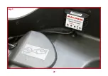
Страница 27: ...27 ITALIANO ENGLISH FRANÇAIS DEUTSCH Fig 1 ...

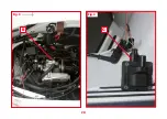
Страница 28: ...28 ITALIANO ENGLISH FRANÇAIS DEUTSCH Fig 2 A ...

Страница 29: ...29 ITALIANO ENGLISH FRANÇAIS DEUTSCH Fig 3 Fig 4 B C ...

Страница 30: ...30 ITALIANO ENGLISH FRANÇAIS DEUTSCH Fig 5 ...

Страница 31: ...31 ITALIANO ENGLISH FRANÇAIS DEUTSCH Fig 6 A ...

Страница 32: ...32 ITALIANO ENGLISH FRANÇAIS DEUTSCH Fig 6 B ...

Страница 33: ...33 ITALIANO ENGLISH FRANÇAIS DEUTSCH Fig 6 C ...

Страница 34: ...O ENGLISH FRANÇAIS DEUTSCH Cablaggio originale Original wiring Cablage d origine Originalverkabelung Modifica necessaria Necessary modification Modification necessaire Erforderliche modifikation Fig 7 Art 5514780 ...

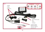
Страница 35: ...ITALIANO ENGLISH FRANÇAIS DEUTSCH Fig 8 Iniettore Injector Injecteur Einspritzung Connettore Diagnosi Diagnosis Connector Connecteur Diagnostic Diagnosestecker Bobina Dell accensione Coil Bobine Zündspule ...

Страница 36: ...36 ITALIANO ENGLISH FRANÇAIS DEUTSCH 06 2021 7315723 Our Ignition Controllers Univers Accensioni Centraline Ignitions Controllers Allumages Boîtiers Zündeinheiten Zündboxen CENTRALINEELETTRONICHE ...

Отзывы: