background image

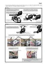
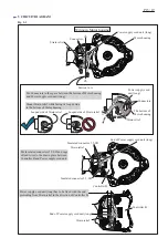
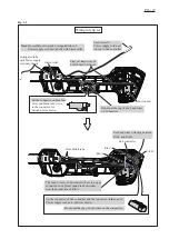
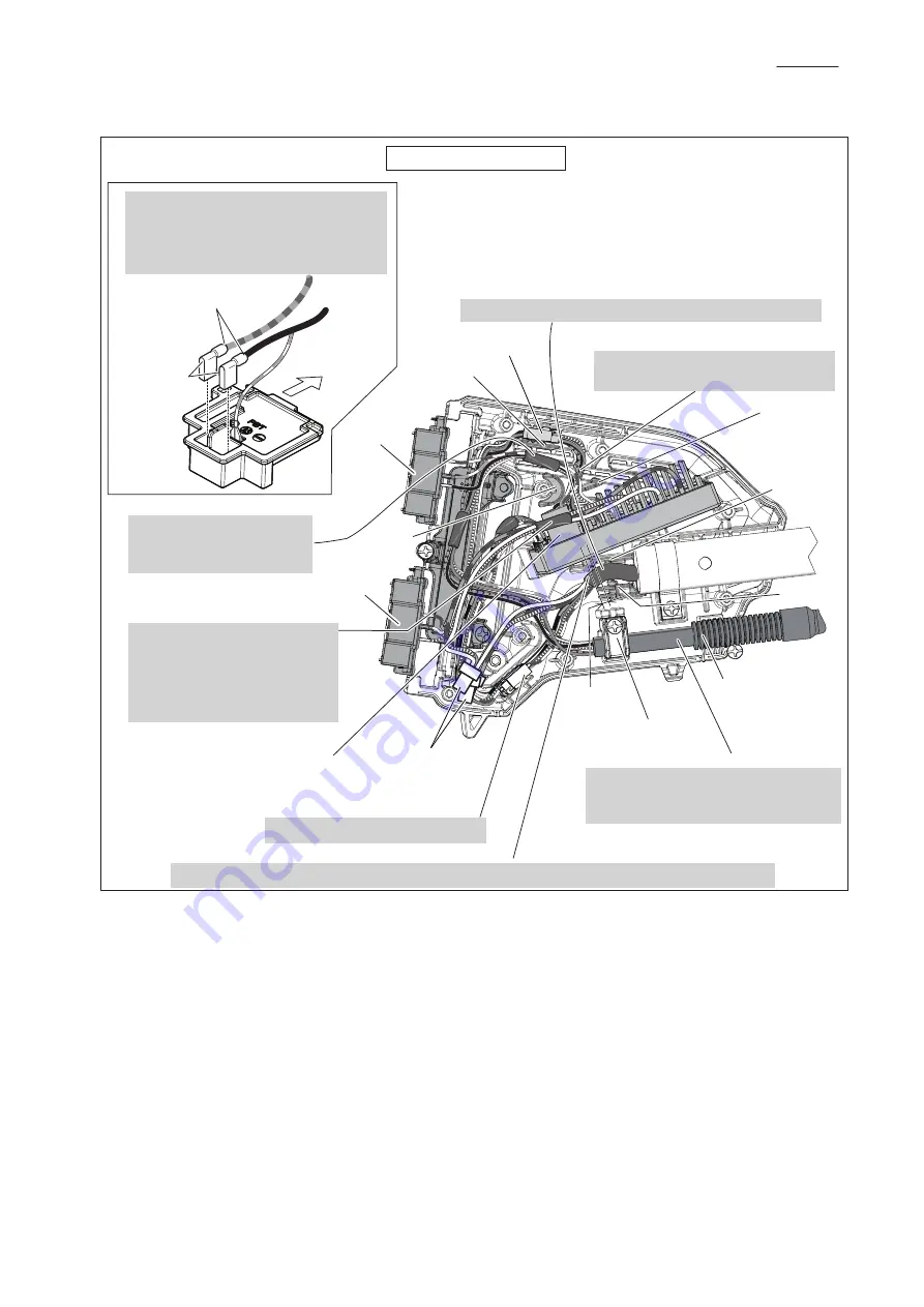
Fix Power supply cord unit (long) by pulling out at least 3 mm from the end of Rib D as shown. 

Flag receptacles of Terminal A and 

Terminal B have to be connected

so that their wire connecting portions 

are located over the marks of + - poles.

Housing L side

Terminal A

Terminal B

Wire connecting portions

3 mm

Corrugated tube

Strain relief

Power supply cord unit (short)


Controller

Rib A

Rib B

Rib C

Rib D

Rib E

Flag 

receptacles

P 17/ 19

Fig. 5-3

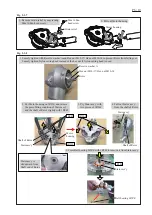
Put Power supply cord (long) between Rib D and Rib E.

Put lead wires with Insulated 

connectors 5.5-SD in front 

of Noise suppressor.

 (between Noise suppressor 

and Housing R)

Put lead wires of Terminals

between Rib A and Rib B,

and Rib B and Rib C.

Put Lead wires for 10 pin Connector 

between Rib B and Rib C. 

Place 2 pin / 5 pin connectors here.  

Wiring in Housing set

Insulated 

connectors

5.5-SD

10 pin Connector

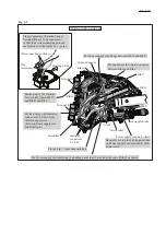
Be careful not to pinch Corrugated tube

on Power supply cord unit (short)


with 

Strain relief .

Содержание XRU09

Страница 1: ...REPAIR MANUAL XRU09...

Страница 2: ...ns Code No Description Use for press fitting Ball bearing 6001DDW press fitting Ball bearing 6001DDW press fitting Stator ass y press fitting Stator ass y press fitting Rotor Pipe ring for Arbor press...

Страница 3: ...Cutter blade Tipped saw blade Cutter blade Tipped saw blade Clamp washer Cup Cutter blade Tipped saw blade 1 Hold Rotor by inserting Hex wrench into the side hole of Motor housing Remove Nylon cuttin...

Страница 4: ...3 pcs M4x16 Pan head screw 2 pcs Controller B 5 Cut three Insulated connectors 5 5 SD at the position marked with red lines Inner cover M5x25 Hex socket head bolt 3 Remove Controller B and Inner cove...

Страница 5: ...ig 2 1 6 1 Cut the tip of plastic portion 2 Cut the skirt portion 3 Cut the drum portion 4 Remove Plastic cover F 5 Pull Lead wires slowly while forming the sleeve to cylindrical figure with water pum...

Страница 6: ...f Rotor Shaft of Rotor Stator ass y Stator ass y Strain relief M4x16 Pan head screw Motor housing Motor housing 1R350 1R045 1R263 1 Loosely tighten with Receive washer A and Hex nut M10 17 Hex nut M10...

Страница 7: ...1R291 Retaining ring R 28 Ball bearing 6001DDW 1R028 Fig 2 1 9 Ring 14 Rotor Rotor 1 Remove Rotor and Ring 14 from Motor housing with 1R045 Note Hook the jaws of 1R045 to Motor housing and set the ce...

Страница 8: ...s y 1R023 1R031 Motor housing Fig 2 2 1 1 Remove sheathes by 13mm from the tip 2 Remove enamel with abrasive paper 100 by 11mm from the tip Note It is necessary to remove enamel to conduct electricity...

Страница 9: ...magnet power Mount Stator ass y while aligning its hole to the locating pin on Motor housing 5 Mount Stator ass y to Motor housing Fig 2 2 4 2 Set Motor housing on 1R033 Apply 1R026 on Stator ass y an...

Страница 10: ...ely from the lead wires of Controller complete cut three Insulated connectors 5 5 SD at the portion designated with red lines Note Cut each clamped portion to leave the lead wires because of the easy...

Страница 11: ...housing complete and then remove the clamped Power supply cord unit 3 Pull out the power supply cord unit toward Housing set side with care of the connector that is passed through Pipe complete 2 Remo...

Страница 12: ...Assemble two holes side of Pipe complete to Housing L with 4x18 Tapping screw and Clamp 24 Housing and Grip set side Motor housing side 3 Loop handle set Pipe complete Grip set Switch lever Lock off l...

Страница 13: ...following four pictures Projection of Lock off lever Groove in Grip L Viewed from the inside Lock off lever Rib of Grip L Groove of Grip L Switch lever 4 Insert Switch lever over the pin of Grip L unt...

Страница 14: ...Symbol Electrical Parts Straight receptacle with polyolefin tube Controller Terminal A Terminal B Battery fuel gauge Power supply cord unit short with corrugate tube Purple Gray Color index of lead w...

Страница 15: ...ooped side to the bottom of Motor housing Insulated connector 5 5 SD Insulated connector 5 5 SD Power supply cord unit long has to be fixed with the end protruding from Strain relief in the direction...

Страница 16: ...b C Rib B Rib A Heat shrink tube Sub controller Corrugated tube with Power supply cord unit short Strain relief Note Be careful not to pinch Corrugated tube of Power supply cord unit short with Strain...

Страница 17: ...ntroller Rib A Rib B Rib C Rib D Rib E Flag receptacles P 17 19 Fig 5 3 Put Power supply cord long between Rib D and Rib E Put lead wires with Insulated connectors 5 5 SD in front of Noise suppressor...

Страница 18: ...r B Sub controller is broken Controller is broken Controller B is broken Replace Controller Incomplete connection of Terminal with battery Check the connection with Battery or Replace Terminal Replace...

Страница 19: ...ontroller Trouble on Controller can be checked with Tester as follows 1 Set Digital tester 1R402 A in the Diode mode 3 Contact Black probe with Terminal Contact Red probe with Terminal Wait until the...

Отзывы: