P 11/ 12
W
iring diagram
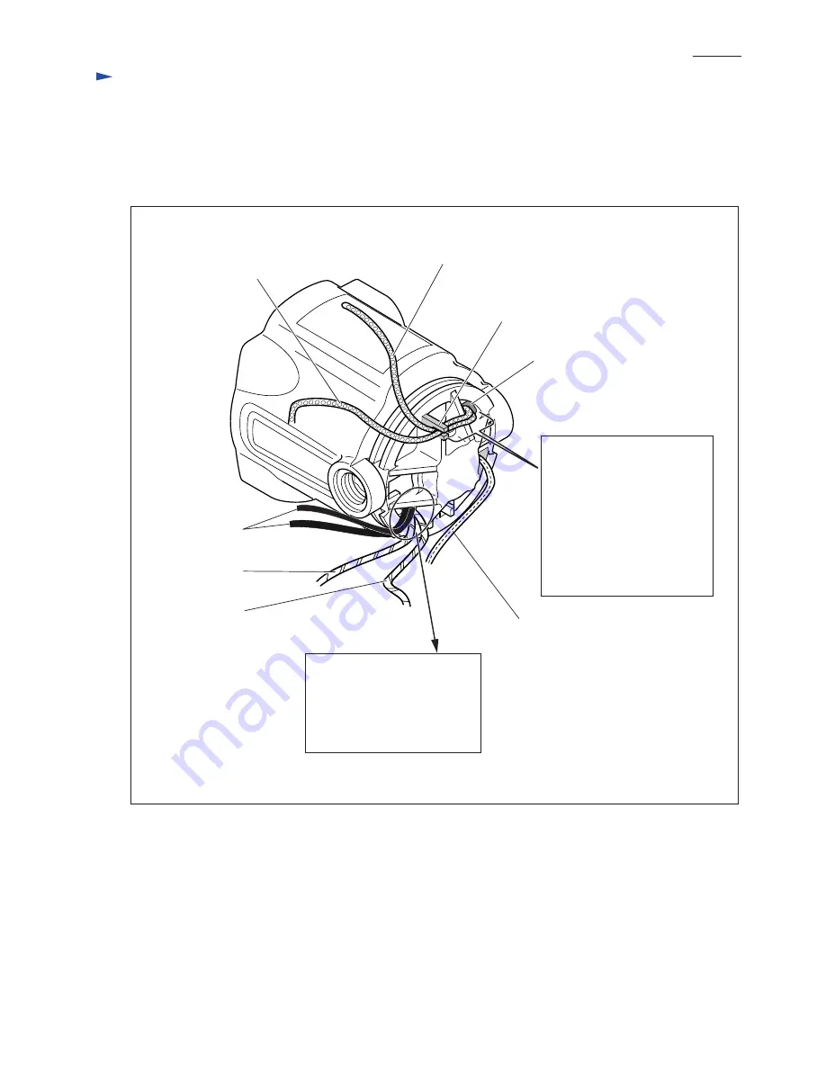
[2] Wiring in Motor Housing (cont.)
[2] -2. Rear side
Fig. 27
Field lead wire (purple)
Lead wire holder
1) Route the following lead
wires through the opening:
*Field lead wire (purple)
*Lead wire from choke coil
to brush holder (purple)
2) Fix the two lead wires with
the lead wire holder.
Be sure that the lead wires
are tight between the opening
and the lead wire holder.
Route the following lead wires
through this opening:
*Field lead wire (orange)
*Lead wire from choke coil
to brush holder (orange)
*Two field lead wires (black)
Opening for lead wires
Lead wire from choke coil
to brush holder (purple)
Field lead wire
(orange)
Field lead wires
(black)
Lead wire (clear)
interconnecting between
noise suppressor and
field core
Lead wire from
choke coil to
brush holder
(orange)
Note: Choke coils are not used except for the following countries:
Taiwan, low voltage of Great Britain


