background image

P 9/13

[3] DISASSEMBLY/ASSEMBLY
[3] -4. Armature, Crank Section

R

epair

Hex socket head bolt

M6x60 (4 pcs)

Hex socket head bolt
M6x20 (2 pcs)

1R045

1R346

Flat washer 6

(4 pcs)

Crank housing
complete

Crank housing
complete

Gear housing
complete

Gear housing
complete

Motor housing

Armature

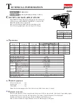
1) Remove the following parts and sections from the machine (Fig. 4 to Fig. 7 in page 4):
    Handle section, Tool holder, Barrel complete, Piston, Connecting rod
2) Remove Rear cover, then disconnect Carbon brushes from Armature commutator as illustrated in Fig. 23.
    Note: No need to take out Carbon brush from Brush holder.
3) Remove Motor housing from Gear housing complete by unscrewing four M6x60 Hex socket head bolts. (Fig. 24)
4) Remove Crank housing complete from Gear housing complete. (Fig. 25)
    Note: Crank section (including Crank shaft, Helical gear 38, etc) still remain in Crank housing complete in this step.
               See page 10 for disassembling of Crank section.
5) Torque limiter assembly can be disassembled from Gear housing complete by tapping the end surface of
    Gear housing complete with plastic hammer. (Fig. 26)
    Important: Do not try to disassemble Torque limiter assembly because it cannot be reassembled once disassembled.
6) Armature can now be disassembled from Gear housing complete using 1R045 and 1R346. (Fig. 27)

Fig. 23

Fig. 24

Fig. 25

Fig. 26

Fig. 27

Torque limiter assembly

DISASSEMBLING

Rear cover

Tapping screw 4x18

(2 pcs)

Remove the end of Spiral spring from Carbon
brush using small slotted screwdriver or the like, 
then pull Carbon brush a little to disconnect
from  Armature commutator.

Disconnecting Carbon brush

from Armature commutator

Spiral spring of Brush holder is pushing in
Carbon brush to contact Armature commutator.

Carbon brush

Spiral spring

of Brush holder

Содержание HR4030C

Страница 1: ...design Continuous rating input W Double insulation Net weight kg lbs Plastic carrying case 1 pc Depth gauge 1 pc Side handle 1 pc Power supply cord m ft Variable speed control Yes Yes Constant speed c...

Страница 2: ...on that engages with Torque limiter Cylindrical portion that contacts Plane bearing of Crank housing complete 22 25 31 33 34 53 55 15 Torque limiter 1R045 Gear extractor large Removing Armature 1R269...

Страница 3: ...r Tool retainer Tool holder center line of the two holes Tool holder Tool holder work bench Tool retainer Fig 2 Fig 2A Model 4030C Damaged Tool retainer can be disassembled from Tool holder by cutting...

Страница 4: ...ts in the same way as described above in the step 2 then pull out Cylinder section from Crank housing complete Fig 6 4 Disconnect Connecting rod from Crank shaft in Crank housing complete then take ou...

Страница 5: ...5 4 in page 4 Note 1 Tool holder is not reversible when assembled to Barrel complete Be sure to assemble as illustrated in Figs 8 8A 2 Do not forget to place O ring 48 between Tool holder and Barrel...

Страница 6: ...n 6 4 pcs Cylinder B Cylinder A Put Cylinder section on work bench with Cylinder B side up Then remove Ring spring 32 using 1R311 while pressing down Flat washer 34 Disassemble Cylinder B from Cylinde...

Страница 7: ...Turn Rubber ring 18 so that it can be seen through the elliptic hole of Cylinder A as illustrated below Washer 17 can be removed in the same way as you did in Removing Rubber Ring 18 Now can be remove...

Страница 8: ...o the assembly of Cylinder A and Cylinder B Fig 22 5 Do the reverse of the disassembling steps Figs 11 to 4 in pages 4 5 6 Fig 21 Cylinder A Rubber ring 18 Slide plate Washer 17 ASSEMBLING Tool holder...

Страница 9: ...section including Crank shaft Helical gear 38 etc still remain in Crank housing complete in this step See page 10 for disassembling of Crank section 5 Torque limiter assembly can be disassembled from...

Страница 10: ...ustrated to right in Fig 29 9 Put Crank housing complete on 1R350 and apply 1R239 to the bottom center of Crank shaft Then disassemble Crank section from Crank housing complete by pressing down 1R239...

Страница 11: ...ndle cover from Handle complete by unscrewing one 4x18 Tapping screw Fig 33 The following electrical parts can now be replaced Switch Power supply cord Cord guard Tapping screw 4x18 1 pc Strain relief...

Страница 12: ...omplete Gear housing complete Motor housing Flat washer 6 4 pcs Flat washer 6 2 pcs Flat washer 4 3 pc Handle complete 8 Item No Size 4 Q ty Used for 7 8 12 0 7 8 12 0 7 8 12 0 7 8 12 0 3 9 5 9 2 9 4...

Страница 13: ...Lead wire of Lead unit white Lead wires must be tight between Switch and Sponge sheet Lead wire of Lead unit black Protective tube Handle complete viewed from rear side 2 3 4 5 Route two Lead wires o...

Отзывы: