


P 10/13
[3] DISASSEMBLY/ASSEMBLY
[3] -4. Armature, Crank Section (cont.)
R
epair
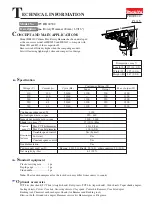
Fig. 31
Crank cap cover
Hex socket head bolt
M4x14 (3 pcs)
Crank cap
Flat washer 4 (3pcs)
Crank housing
complete
Fig. 28
1R269
Helical gear 38
Crank shaft
Retaining ring S-20
Ball bearing 6004LLU
1R291
7) Remove Crank cap cover and Crank cap by unscrewing three M4x14 Hex socket head bolts using 1R228 and
Impact driver. (Fig. 28) Crank section can now be seen in Crank housing complete. (Fig. 29)
8) Align Crank pin of Crank shaft with the notch in Crank housing complete as illustrated to right in Fig. 29.
9) Put Crank housing complete on 1R350, and apply 1R239 to the bottom center of Crank shaft.
Then disassemble Crank section from Crank housing complete by pressing down 1R239 using arbor press. (Fig. 30)
10) Crank section can be disassembled using 1R269 and 1R291 as illustrated in Fig. 31.
Crank housing complete,
viewed from Crank cap cover side
Fig. 29
Crank housing complete
Fig. 30
1R239
1R350
Crank shaft
Crank section
Flat washer 10
DISASSEMBLING
Crank pin of
Crank shaft
notch in Crank
housing complete
Disassembling Crank Section
Do the reverse of the disassembling steps.
Note:
Do not forget to mount O ring 50 and Filter on Crank cap. (Fig. 32)
ASSEMBLING
Crank cap
Filter
O ring 50
Fig. 32
Crank housing
complete


