7 ENGLISH
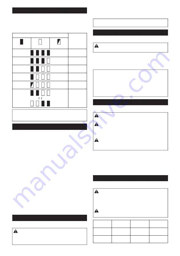
Indicating the remaining battery capacity
Press the check b utton on the b attery cartridge to indi-
cate the remaining b attery capacity . T he indicator lamps
light up for a few seconds.
Fig.2:
1.
Indicator lamps
2.
C heck b utton
Indicator lamps
Remaining
capacity
Lighted
Off
Blinking
7 5 % to 1 0 0 %
5 0 % to 7 5 %
2 5 % to 5 0 %
0 % to 2 5 %
C harge the
b attery .
T he b attery
may hav e
malfunctioned.
NOTE:
Depending on the conditions of use and the
amb ient temperature, the indication may differ slightly
from the actual capacity .
Tool / battery protection system
T he tool is eq uipped w ith a tool/ b attery protection sy s-
tem. T his sy stem automatically cuts off pow er to the
motor to ex tend tool and b attery life. T he tool w ill auto-
matically stop during operation if the tool or b attery is
placed under one of the follow ing conditions:
Overload protection
When the tool is operated in a manner that causes it to draw
an ab normally high current, the tool stops automatically . In this
situation, turn the tool off and stop the application that caused
the tool to b ecome ov erloaded. T hen turn the tool on to restart.
Overheat protection
When the tool is ov erheated, the tool stops automati-
cally and the lamp b links. In this situation, let the tool/
b attery cool b efore turning the tool on again.
Overdischarge protection
When the b attery capacity is not enough, the tool stops
automatically . In this case, remov e the b attery from the
tool and charge the b attery .
Sw itch action
Fig.3:
1.
S w itch trigger
CAUTION:
Before installing the battery car-
tridge into the tool, alw ays check to see that the
sw itch trigger actuates properly and returns to
the " OFF" position w hen released.
T o start the tool, simply pull the sw itch trigger. T ool
speed is increased b y increasing pressure on the sw itch
trigger. Release the sw itch trigger to stop.
NOTE:
T he tool automatically stops if y ou keep pull-
ing the sw itch trigger for ab out 6 minutes.
Lighting up the front lamp
Fig.4:
1.
Lamp
CAUTION:
Do not look in the light or see the
source of light directly.
Pull the sw itch trigger to light up the lamp. T he lamp
keeps on lighting w hile the sw itch trigger is b eing pulled.
T he lamp goes out approx imately 1 0 seconds after
releasing the sw itch trigger.
NOTE:
When the tool is ov erheated, the tool stops
automatically and the lamp starts flashing. In this
case, release the sw itch trigger. T he lamp turns off in
one minute.
NOTE:
U se a dry cloth to w ipe the dirt off the lens of
the lamp. Be careful not to scratch the lens of lamp, or
it may low er the illumination.
Reversing sw itch action
Fig.5:
1.
Rev ersing sw itch lev er
CAUTION:
Alw ays check the direction of
rotation before operation.
CAUTION:
Use the reversing sw itch only after
the tool comes to a complete stop.
C hanging the
direction of rotation b efore the tool stops may dam-
age the tool.
CAUTION:
W hen not operating the tool,
alw ays set the reversing sw itch lever to the neu-
tral position.
T his tool has a rev ersing sw itch to change the direction
of rotation. Depress the rev ersing sw itch lev er from the
A side for clockw ise rotation or from the B side for coun-
terclockw ise rotation.
When the rev ersing sw itch lev er is in the neutral posi-
tion, the sw itch trigger cannot b e pulled.
Speed change
Fig.6:
1.
S peed change lev er
CAUTION:
Alw ays set the speed change lever
fully to the correct position.
If y ou operate the
tool w ith the speed change lev er positioned halfw ay
b etw een the " 1 " side and " 2 " side, the tool may b e
damaged.
CAUTION:
Do not use the speed change lever
w hile the tool is running.
T he tool may b e damaged.
Displayed
Number
Speed
Torque
Applicable
operation
1
Low
H igh
H eav y load-
ing operation
2
H igh
Low
Light loading
operation
Содержание HP001G
Страница 2: ...1 2 3 Fig 1 1 2 Fig 2 1 Fig 3 1 Fig 4 1 B A Fig 5 1 Fig 6 1 3 2 Fig 7 2 1 3 4 Fig 8 2 ...
Страница 3: ...1 2 3 Fig 9 3 2 4 1 Fig 10 2 1 Fig 11 3 2 1 Fig 12 1 2 Fig 13 Fig 14 1 Fig 15 1 Fig 16 3 ...
Страница 37: ......
Страница 38: ......
Страница 40: ...IDE 8 8 5 7 6 5 5 0 8 3 1 7 2 0 1 9 Makita E urope N V Ja n Baptist Vinkstraat 2 3 0 7 0 K ortenb erg Belgium ...
Страница 42: ...1 2 3 Fig 1 1 2 Fig 2 1 Fig 3 1 Fig 4 1 Fig 5 1 A B Fig 6 3 1 2 Fig 7 1 Fig 8 2 ...
Страница 43: ...Fig 9 Fig 10 1 2 Fig 11 Fig 12 3 ...
Страница 44: ...1 2 Fig 13 1 3 2 Fig 14 3 2 1 Fig 15 Fig 16 4 ...
Страница 94: ......
Страница 96: ...IDE 8 8 5 7 6 9 5 0 0 3 9 2 0 1 9 Makita E urope N V Ja n Baptist Vinkstraat 2 3 0 7 0 K ortenb erg Belgium ...


