background image


37 / 71 

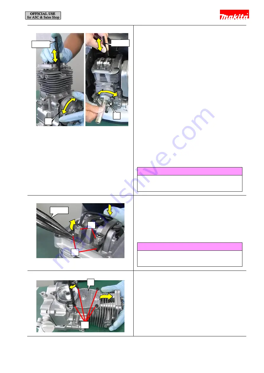
Fig. 77 


3


For easy removal of Rod 2.5 from Rocker arm, 

position Piston at compression top dead center as 

follows: 

1


Remove Spark plug and then insert 1R411 

through the spark plug hole. 

2


Turn Flywheel [1] until Piston reaches the 

highest position. (Turn Pulley [2] instead of 

Flywheel [1] if the blower body is assembled to 

the backpack frame.) 

3


Turn Flywheel [1] (or Pulley [2]) 45 degrees left 

and right to confirm the position of Piston. 

4


If Valve does not move, Piston is positioned at 

compression top dead center. If Valve moves, 

Piston is positioned at exhaust top dead center. 

In this case, bring Piston to compression top 

dead center by turning Flywheel [1] (or Pulley 

[2]) 360 degrees. 


Tips 

This method to find compression top dead center can 

be applied to our all 4-stroke engines. 


Fig. 78 


4


Remove Rod 2.5 (2 pcs) [2] as follows. Insert a 

Hex wrench 2.5 into M5x9 Hex socket set screw 

[1]. Then, while pushing down the wrench to raise 

the screw, pull Rod 2.5 [2] out of Cylinder with 

1R311. 


Tips 

Rod 2.5 [2] can also be removed in the step of 

removing Cam gear cover. 


Fig. 79 


5


Remove four M5x20 Hex socket head bolts [1] to 

remove Cam gear cover [2] and Cam gear cover 

gasket. 

[2] 

[1] 

[1] 

[2] 

1R311 

[2] 

1R411 

1R411 

[1] 

Содержание EB5300TH

Страница 1: ...April 2017 Ver 1 PETROL BLOWER EB5300TH TUBE MOUNTED THROTTLE EB5300THG TUBE MOUNTED THROTTLE EB5300WH HIP MOUNTED THROTTLE REPAIR MANUAL...

Страница 2: ...ssembling Control arm for Model EB5300WH 26 4 5 Engine section 28 4 5 1 Disassembling Engine 28 4 5 2 Disassembling Muffler 29 4 5 3 Assembling Muffler 29 4 5 4 Disassembling Engine continued 30 4 5 5...

Страница 3: ...k if it moves smoothly without abnormal noise by manually turning the crankshaft After completion of reassembly check for loose parts or abnormal noise and vibration by manually turning the crankshaft...

Страница 4: ...like to remove grease from the mating surface of Cylinder and Crankcase and then apply Liquid gasket ThreeBond 1215 Fig 1 Note When removing grease do not directly spray parts cleaner to the rubber p...

Страница 5: ...tapered portion Lubricant Amount Makita grease FA No 2 a little 4 stroke engine oil a little Fig 2 Outer circumference of Cam lifter Outer circumference of Push rods Tips of valves and sliding portio...

Страница 6: ...e by pushing Primer pump repeatedly Drain the oil when the machine is disassembled down to Engine block Refer to Fig 60 Fig 3 2 Remove Intermediate pipe Long pipe or Short pipe from Swivel pipe comple...

Страница 7: ...ame can be removed by turning the center lock pin 2 of the rivet counterclockwise with a Phillips screwdriver to lift up the pin Tips If the center lock pin 2 spins freely and cannot be lifted up turn...

Страница 8: ...ne section and to remove Control arm Refer to 4 4 3 Do not fail to remove the two bolts fastening Fuel tank Fig 10 2 Remove four Compression springs 22 damper springs 1 by turning them counterclockwis...

Страница 9: ...Fig 14 6 Remove five 5x20 Tapping screws 1 to remove Engine cover complete 2 7 Remove Plug cover 3 Fig 15 8 Disconnect two Straight terminals 1 of Lead unit Note When you pull off Straight terminal 1...

Страница 10: ...osen two M5x20 Thumb screws 1 to remove Air cleaner cover 2 and Air cleaner element 3 Fig 18 11 Remove Fuel tube 3 370 black 1 from Carburetor 2 with 1R311 Fig 19 12 Remove Fuel tube 3 370 clear 1 fro...

Страница 11: ...1 so that it does not rotate back and then pull out Starter rope 4 from the triangular gap between Recoil starter 2 and Reel 1 Fig 23 3 Hook Starter rope 1 on the U shaped notch of Reel 2 and then tur...

Страница 12: ...12 71 Fig 25 5 Remove two Swing arms 1 from Collar 2 1 2...

Страница 13: ...ter 1 and placed in Reel 2 Fig 27 2 When Spiral spring 1 is removed for repair or accidentally pops out of Reel 2 fit it back in place as follows 1 Hook the outer end of the spring into the notch 3 of...

Страница 14: ...knob 2 Tie the knot in Starter rope 1 Each length a should be approximately 10mm 2 Wind the other end of Starter rope on Reel leaving approximately 200mm unwound Fig 29 3 Put Reel 1 into Recoil start...

Страница 15: ...Reel wind up Starter rope into Recoil starter Fig 32 7 Make sure that Starter rope 1 is wound up with an optimum tension Note Starter knob 2 should get upright by itself if you let go of it and Reel...

Страница 16: ...not to break Cap holder 3 of Fuel tank cap assembly 1 Be sure to hook your finger on Cap holder 3 and then pull it out of Fuel tank Fig 35 2 Push Grommet 1 into Fuel tank 2 with a Phillips screwdriver...

Страница 17: ...37 2 With a slotted screwdriver assemble Grommet 1 to Fuel tank Note The clear Tube should be placed to the fuel filler opening side and all the three Tubes should be on the red dotted line Fig 38 3 I...

Страница 18: ...n relieves Refer to Fig 15 and Fig 16 Fig 39 2 With a slotted screwdriver pry up the locking tab to remove Carburetor cover 1 Fig 40 3 Turn Throttle 1 clockwise and hold it there with your finger Then...

Страница 19: ...ng 4 2 from Lever case L 3 and then disconnect the barrel nipple of Control cable from Throttle lever A 1 Fig 43 4 Release the corrugated tube and remove Leaf spring A 1 B 2 with long nose pliers Tips...

Страница 20: ...20 71 6 Pull Control cable and Lead unit out of Corrugated tube Tips First pull out the wire of Control cable and then one by one pull out the two lead wires with Straight terminal of Lead unit...

Страница 21: ...able 1 from the end with the white marking Fig 46 2 Assemble Control lever by reversing the disassembly procedure 3 Install Leaf spring A 1 and Leaf spring B 2 so that Throttle link 3 4 Fix the lead w...

Страница 22: ...when Control lever B 1 is set to O and that there is no conduction when Control lever B 1 is set to I Tips By attaching 1R402 B to the tip of each probe of 1R402 A you can do the check easily with cl...

Страница 23: ...section 2 from Frame 3 Fig 49 3 Remove M6x25 Hex socket head bolt 1 to remove Arm 2 and Arm base section 3 In this step Sleeve 7 4 and Flat washer 12 5 are also removed Fig 50 4 Using a slotted screwd...

Страница 24: ...Fig 53 7 Remove six 4x18 Tapping screws 1 to remove Arm cover 2 Fig 54 8 Disconnect the connector of Lead unit and then push Switch unit 1 out of Arm cover 2 with 1R311 Fig 55 9 Remove Corrugated tub...

Страница 25: ...ved Fig 57 11 Using 1R402 A make sure that there is conduction when Control lever is set to O and that there is no conduction when Control lever is set to I Tips By attaching 1R402 B to the tip of eac...

Страница 26: ...bly procedure Fig 58 2 The orientation of the two Torsion springs 21 1 matters Put the spring in the spring chamber of Arm base 2 with the short leg on the far side 3 Fit the long leg of Torsion sprin...

Страница 27: ...y c 7 Put Connector 5 in the space indicated by d 8 Fix the lead wires 6 of Lead unit in the lead wire holders indicated by e 9 Put Control cable 7 in the space indicated by f 10 Put Corrugated tube 8...

Страница 28: ...cording to Fig 13 and Fig 14 remove Recoil starter and Engine cover complete Fig 60 2 Remove M8x12 Hex bolt drain bolt 1 to drain Oil case Note Be careful not to lose Gasket washer 2 Fig 61 3 Remove t...

Страница 29: ...n head screw 1 and then remove Tail plate 2 and Spark arrester 3 out of Muffler Tips If there are carbon deposits on Spark arrester 3 remove them with commercial carbon remover 4 5 3 Assembling Muffle...

Страница 30: ...on head bolts 1 3 Remove 5x20 Tapping screw 2 4 Disconnect Tube 5 55 5 from the nipple 6 of Blowby guide with 1R311 5 Disconnect Fuel tube 3 85 transparent 7 from Carburetor 8 6 Remove Carburetor 8 Ca...

Страница 31: ...d remove Insulator 2 10 With 1R311 remove Oil tube 5 195 3 and Tube 5 55 4 from Cylinder block Fig 67 11 Remove the following parts 4x18 Tapping screw 1 Icing valve 2 Fuel suction line 3 Carburetor br...

Страница 32: ...let screen be careful not to deform it 5 Use air duster as little as possible or it may break the inner parts of Carburetor such as Check valve Note Once Metering diaphragm gasket 4 or Pump gasket 8 i...

Страница 33: ...place them with new ones 4 While pressing down Lever 1 install Screw 2 and then make sure that Lever 1 is movable 5 Match the two holes of Pump gasket and Pump diaphragm 3 with the positioning pins of...

Страница 34: ...r the assembling completed condition in the case of EB5300TH it indicates that Control lever is installed on Swivel pipe complete without twist in the cable 8 Check Carburetor for air leaks Connect th...

Страница 35: ...king claws of Primer pump 1 to unlock from Cleaner case Primer pump can now be removed 4 5 8 Assembling Air Cleaner plate Fig 74 1 Assemble Air cleaner case by reversing the disassembly procedure 2 Se...

Страница 36: ...3 will interfere with removal of the bolt on the far side So remove Oil case 3 or use an L shaped hex wrench 4 to loosen the bolt Use 1R181 to check Ignition coil 2 Refer to 4 5 10 for details on how...

Страница 37: ...on top dead center If Valve moves Piston is positioned at exhaust top dead center In this case bring Piston to compression top dead center by turning Flywheel 1 or Pulley 2 360 degrees Tips This metho...

Страница 38: ...ge Flyweight is normal if you can push it in easily with finger and if it returns to the initial position easily Fig 82 8 Remove Pulley 1 by turning counterclockwise with an impact driver and Socket b...

Страница 39: ...rotect the threads of Crankshaft Fig 85 11 Remove Spark plug CMR6H 1 with Box wrench 16 Fig 86 12 Remove four M5x20 Hex socket head bolts 1 to remove Oil case 2 Fig 87 13 Remove M5x20 Hex socket head...

Страница 40: ...89 Tips Crankcase 3 and Cylinder block 4 are securely joined together with liquid gasket So after removing the bolts insert a slotted screwdriver into the gap of the mating face and then turn the scre...

Страница 41: ...it with a new one Fig 92 17 Prevent Intake valve and Exhaust valve from dropping by following the procedure as follows 1 Clamp a plastic hammer securely in a vise 2 Wrap a rag around the handle of the...

Страница 42: ...Fig 95 20 From Piston remove Top ring 1 Second ring 2 Oil ring 3 21 From Crankshaft remove the following parts Oil seal 15 4 Two different ones are used and the one on Key installation side has a larg...

Страница 43: ...43 71 Fig 98 23 Woodruff key 4 1 can be removed by clamping it in a vise then by pulling up Crankshaft 2 1 2...

Страница 44: ...e The conventional method to check directly for spark with Spark plug attached on the outside of Cylinder is uncertain and therefore prohibited Persons with a pacemaker should not use this checker Do...

Страница 45: ...until the engine speed reaches a certain level B Check through Spark window that bluish white sparks are certainly generated ten consecutive times And replace Ignition coil with a new one if there is...

Страница 46: ...il will be overloaded and broken 1 Attach Alligator clip onto Spark plug 2 Set Spark gap adjusting knob to 4mm 3 Start the engine and check that sparks are generated consecutively from idling to the m...

Страница 47: ...e Fig 100 3 Apply a little amount of 4 stroke engine oil to the tips of Intake valve and Exhaust valve 1 and then insert them into Cylinder block 2 Fig 101 4 Prevent Intake valve and Exhaust valve fro...

Страница 48: ...parts of Oil ring 2 should be at 120 degrees to one another Tips The orientation of Second ring matters When the ring is installed on Piston 3 the white paint mark should be located on the right side...

Страница 49: ...el to the tapered surface of Crankshaft Fig 108 12 When assembling Cylinder block and Crankcase apply a thin layer of Liquid Gasket ThreeBond 1215 evenly to the mating surface the portions indicated b...

Страница 50: ...numerical sequence as shown on the left Fig 112 16 Put Reed valve 1 on Crankcase U shaped notch of the valve must be aligned with the rib of Crankcase Fig 113 17 By tightening M5x20 Hex socket head bo...

Страница 51: ...hen turn Flywheel 2 until Piston stops Note Remove any grease from the tapered portion of Crankshaft with parts cleaner Fig 116 20 Install Flywheel 1 onto Crankshaft and then fasten with Flange nut M1...

Страница 52: ...der block Crankcase 3 Fig 119 24 Install Cam gear ass y 1 and Cylinder block 2 while aligning the matching marks of the two parts and then insert Pin 5 through Cam gear ass y 1 into Cylinder block Fig...

Страница 53: ...crew 1 Then while raising Rocker arm 2 pcs 2 by pushing down near the end of the long arm of the wrench install Rod 2 5 2 pcs 3 with 1R411 in place Fig 123 28 By tightening four M5x20 Hex socket head...

Страница 54: ...to confirm the position of Piston 4 If Rocker arm does not move Piston is positioned at compression top dead center If Rocker arm moves Piston is positioned at exhaust top dead center In this case bri...

Страница 55: ...f Insulator 2 Note Be careful not to bend Oil tube 5 195 3 at each of the top and bottom curves Fig 129 37 Connect Fuel tube 3 85 transparent 1 to Carburetor 2 and Tube 5 55 3 to the nipple 8 of Blowb...

Страница 56: ...head bolts fasten Muffler 1 and Muffler gasket 2 to Cylinder block Note Do not reuse Muffler gasket 2 Be sure to replace it with a new one The bolt holes can be easily misaligned in tightening operat...

Страница 57: ...en two M4x20 Hex socket head bolts 1 to fasten Ignition coil 2 to Crankcase Fig 135 47 Pass High voltage cable 1 through the hole of Insulator 2 and then install Spark plug cap 3 onto Spark plug CMR6H...

Страница 58: ...ead bolts 1 and two Tapping screws 2 fasten Front volute case 3 to Cylinder block Fig 137 2 By tightening four M6x25 Hex socket head bolts 1 fasten Fan 243 2 to Flywheel Tips Align the matching mark t...

Страница 59: ...springs 22 1 are used Install two black ones on the Cushion side of Frame and two silver ones on the bottom side of Frame Be careful not to mix up the two springs When assembling Compression spring 22...

Страница 60: ...of Swivel 3 If it is oriented wrong the barrel nipple cannot be attached Fig 143 3 Fix Control cable 3 in Clamp 2 by tightening 4x14 Tapping screw 1 Note Position Corrugated tube 4 so that the end fa...

Страница 61: ...2 Connect two Straight terminals 1 of Lead unit with those from Ignition coil and Earth terminal and then put the terminals and Corrugated tube 2 in the space of Front volute case 3 Tips Position Corr...

Страница 62: ...nipple of each part until it stops Fig 150 6 Put Plug cover 1 and Engine cover complete 2 on the engine section and then fasten them with 5x20 Tapping screw 5 pcs 3 magnetized with 1R288 Fig 151 Note...

Страница 63: ...may find that one or two rivet legs are not closed If you push in the rivet without closing the legs the legs will be broken 12 Attach Band completes L and R to Frame by pushing Lock rivet through ea...

Страница 64: ...d Intermediate pipe Long pipe or Short pipe on Swivel pipe Note Be sure to check engine speed with 1R070 and with End nozzle 90 62 nozzle diameter 61 5mm on Intermediate pipe Without the nozzle engine...

Страница 65: ...ust screw if Throttle of Carburetor does not move to the full throttle or idling position even though you operate Throttle lever in the condition of assembly completed which indicates in the case of M...

Страница 66: ...eaner plate Insulator 5x20 Tapping screw 2 2 2 7 1 Adjust screw M6 Hex nut 1 0 2 0 1 Pulley Crank shaft Pulley M8 9 0 11 0 1 Oil pipe Oil case M5x20 Hex socket head bolt 4 5 6 5 2 Oil cap Oil pipe 0 4...

Страница 67: ...157 AWG American wire gauge Lead unit B Lead unit A Leaf spring A or B Lead unit B Lead unit A Black AWG20 Black AWG20 Ignition coil Lead unit B Connector black Black AWG20 Black AWG20 Lead unit A Le...

Страница 68: ...rm section 7 1 1 EB5300TH Tube throttle model Fig 158 Fix the lead wires in these lead wire holders I O Put Controller lead wires and Corrugated tube in these lead wire holders Throttle lever should b...

Страница 69: ...nit from Switch terminal 1 should be put in Rib A and the inner wall Put Controller lead wires and Corrugated tube in this space Rib C Rib B Put the slack of the lead wires of Switch unit in this spac...

Страница 70: ...Projection A Controller lead wire Put the slack of the lead wires from Leaf spring A B in this space The high voltage cable should be routed over the other lead wires The end of Corrugated tube shoul...

Страница 71: ...71 71 7 2 1 Routing of Corrugated tube Fig 161 EB5300TH Corrugated tube should be put into this space EB5300WH Corrugated tube should be put into this space...

Отзывы: