13
013900
Nylon cutting head
NOTICE:
• Do not attempt to bump feed the head while the tool is
operating at a high RPM. Bump feeding at a high RPM
may cause damage to the nylon cutting head.
• The bump feed will not operate properly if the head is
not rotating.
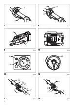
(Fig. 12)
The nylon cutting head is a dual grass trimmer head
provided with a bump & feed mechanism.
To cause the nylon cord to feed out, the cutting head
should be bumped against the ground while rotating at a
low RPM.
NOTE:
If the nylon cord does not feed out while bumping the
head, rewind/replace the nylon cord by following the
procedures described under “Maintenance”.
ASSEMBLY
WARNING:
•
Always be sure that the tool is switched off and
battery cartridge is removed before carrying out
any work on the tool.
Failure to switch off and remove
the battery cartridge may result in serious personal
injury from accidental start-up.
•
Never start the tool unless it is completely
assembled.
Operation of the tool in a partially
assembled state may result in serious personal injury
from accidental start-up.
Mounting the attachment pipe
Only for model DUR183L (Fig. 13)
To mount the attachment to a power unit:
1. Make sure that the lever is not tightened.
2. To open the entrance of the joint, depress the joint
cover.
(Fig. 14)
3. Align the protrusion on the pipe (cutting tool side ) with
the concave portion of the joint part.
4. Insert the attachment pipe into the joint part. Make
sure that the surface of the lock lever is horizontal to
the pipe.
5. Tighten the lever firmly as shown.
To remove the attachment, loosen the lever, press the
front part of the lock lever and then slide the pipe.
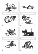
Installing the grip (Fig. 15)
Fit the grip onto the shaft pipe and tighten it with two hex
bolts. Make sure that the spacer on the shaft pipe is
located between the grip assembly and the other grip. Do
not remove or shrink the spacer.
CAUTION:
• For model DUR183L, never install the grip on the joint.
Installing the guard
WARNING:
•
Never use the tool without the guard illustrated in
place.
Failure to do so can cause serious personal
injury.
(Fig. 16 & 17)
Align the protrusions on the protector with the grooves of
the motor housing.
(Fig. 18)
Align the protrusions on the protector holder with the
concave portions of the motor housing. Insert the
protector holder to the motor housing.
(Fig. 19)
After attaching the protector and the protector holder to
the motor housing, tighten the hex bolts securely.
Installing the wire guard
CAUTION:
• Before adjusting the wire guard, wait for the cutting
head comes to standstill. Do not adjust the wire guard
with your foot.
(Fig. 20)
To reduce the risk damaging the objects in front of the
cutting head, insert the wire guard so that it controls the
cutting range of the mowing line.
(Fig. 21)
Slightly expand the wire guard outward and then insert it
into the holes of the protector.
NOTE:
• Do not expand the wire guard outward too much.
Otherwise it may break.
(Fig. 22)
When wire guard is not in use, lift it for the idle position.
Installing nylon cutting head
NOTICE:
• Be sure to use genuine Makita nylon cutting head.
Turn the tool upside down so that you can replace the
nylon cutting head easily.
(Fig. 23)
Insert the hex wrench through the hole on the protector
cover and the motor housing and rotate the receive
washer until it is locked with the hex wrench. Mount the
metal guard, the nylon cutting head onto the threaded
Power indicator
Battery indicator
Status
Action to be taken
Blinking
Battery power has been nearly used
up.
Replace the battery with fully charged
one.
Lighting up
Battery protector is shutting off the
power - battery power has been used
up.
Replace the battery with fully charged
one.
Blinking
Overheat protector is shutting off the
power - overheating.
Rest and cool down the equipment for
a while.
Содержание DUR183L
Страница 2: ...2 1 010820 2 010821 3 012858 ...
Страница 7: ...7 31 013825 32 013826 33 013827 ...
Страница 25: ...ALA Makita Corporation Anjo Aichi Japan 885230A999 www makita com ...


