5-2
Rotor, Switch, Controller, Stator
5-2-1
Disassembling
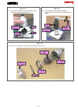
[1] Remove Rotor, and remove Housing R. (5-1-1 Disassembling)
[2] Remove Switch, Controller and Stator.
5-2-2
Assembling
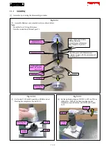
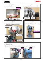
[1] Assemble by reversing the disassembly procedure.
[2] Be careful to check the points mentioned in
Fig. 5-2-2-1
,
Fig. 5-2-2-2
.
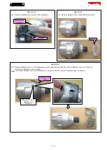
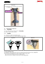
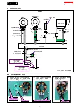
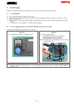
Caution for Handling of Rotor
When handling or storing multiple Rotors, be sure to keep a proper distance between Rotors as shown in
Fig. 5-2-2-1
.
Because Rotor has strong magnetic force, failure to follow this instruction could result in:
·
Finger injury caused by pinching between Rotors pulling each other
·
Magnetic loss of Rotors or damage on the magnet portion of Rotor (
Fig. 5-2-2-2
)
Fig. 5-2-2-1
Fig. 5-1-2-9
[10] Assemble Rear cover to Housing set with two Bind PT
3x16 Tapping screws.
Bind PT 3x16 Tapping
screw (2 pcs.)
Rear cover
Fig. 5-2-2-2
9 / 19

