


8
Troubleshooting
Whenever you find any trouble in your machine, first, refer to this list to check the machine for solution.
8-1
Note in Repairing
(1) Use the full charged battery which has the star mark.
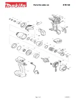
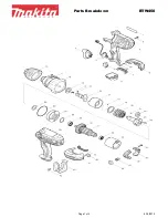
(2) When Housing is disassembled, check the conditions of the electrical parts (Connectors, Lead wires, Switches, etc.), Rotor,
Stator, Gear section, etc.
(3) Do the running test in Soft mode (when the trigger is being pulled just a little) to check the following functions by repeating
10 times;
•
F/R change lever
•
Switch plate
•
Variable speed control trigger
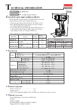
8-2
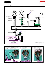
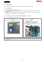
Test for recognizing the short-circuit of FET (Field Effect Transistor) on controller
Trouble on Controller can be checked with Tester as follows.
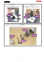
Fig. 8-2-1
[1] Set Digital tester (1R402-A) in the Diode mode.
Fig. 8-2-2
[2] First, remove the battery.
Contact Black probe (a) with (+) Terminal (b).
Contact Red probe (c) with (-) Terminal (d).
Wait until the figure on Tester gets stable.
Note:
Be careful not to reverse them. The reversed contacts
could spoil the test.
[3] Controller is in order if Tester indicates 0.7V ~ 0.9V. If Tester indicates 0 V~0.4 V approx., Controller is broken. Replace it
with a new one.
(a)
(b)
(d)
(c)
17 / 19