[3] DISASSEMBLY/ASSEMBLY
[3]-2. Spiral bevel gear 37, Ball bearing 696ZZ / 6201DDW (cont.)
[3]-3. Shaft lock mechanism
(1) Assemble Flat washer 12 and Ball bearing 6201DDW to Bearing box. (Refer to
Fig. 7 of page 5
.)
(2) Secure Ball bearing 6201DDW with Retaining ring R-32. (Refer to
Fig. 7 of page 5
.)
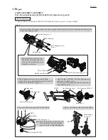
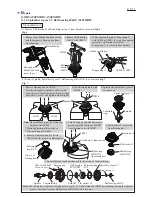
(3) Assemble Spiral bevel gear 37 to Spindle as drawn in
Fig. 8
.
(4) Reverse the disassembly procedure of
Figs. 7 and 6 of page 5
to set Bearing box section in place.
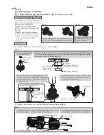
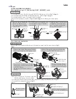
Remove Shaft lock mechanism (Shoulder pin 4, Compression spring 8 and Pin cap) as drawn in
Fig. 9
.
2. Put 1R029 on the area around the center
hole of Spiral bevel gear 37 and then
press it down.
3. Snap Ring spring 11 into the groove
of Spindle to secure Spiral bevel
gear 37, and then assemble Ball
bearing 696ZZ to Spindle.
1. Insert the thread of Spindle into
the hole on 1R036 to receive
the stepped portion of Spindle
as drawn below.
ASSEMBLING
DISASSEMBLING
Fig. 8
Fig. 9
1R036
1R036
Bearing box
Thread of Spindle
Stepped
portion of
Spindle
Spiral bevel
gear 37
Bearing box
1R029
1R036
Ball bearing
696ZZ
Ring spring 11
3. Apply 1R268 to Shoulder pin 4 through
the small hole on Pin cap and tap 1R268
with Metal hammer.
Shoulder pin 4 is removed from Gear
housing.
4. Release 1R268 from Pin cap
carefully so that Pin cap is not
slung by Compression spring 8.
Shoulder pin 4
Pin cap
Note
: Do not reuse Pin cap. It is because removal of
Shoulder pin 4 damages the inside surface.
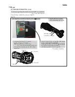
(1) Clean up the plastic dust from Gear housing, Compression spring 8 and Shoulder pin 4. (
Fig. 11
)
(2) Assemble the components as drawn in
Fig. 12
.
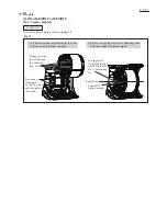
1. Separate Gear section (Gear housing, Bearing
box) by unscrewing four 4x30 Tapping screws.
2. Separate Bearing box section from Gear housing
by unscrewing four M4x14 Pan head screws.
Small hole
of Pin cap
Compression
spring 8
1R350
Gear housing
Gear housing
Bearing box
Bearing box
4x30 Tapping
screws (4 pcs.)
M4x14 Pan head
screws (4 pcs.)
P 6/ 11
ASSEMBLING
Fig. 11
Fig. 12
Be sure to clean up
plastic dust here.
O ring 5
Shoulder pin 4
with O ring 5
Top of Shoulder pin 4
1. Insert Shoulder pin 4 through
the hole of Gear housing complete.
Pin cap
Compression Spring 8
2. Assemble Compression spring 8
and new Pin cap to Shoulder pin 4.
R
epair

