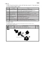


[3] DISASSEMBLY/ASSEMBLY
[3]-1. Rotor, Ball bearing 629LLB, 607LLB, Spiral bevel
gear 10
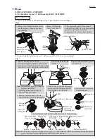
DISASSEMBLING
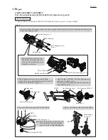
2. Insert Slotted screwdriver into
the notch of Gear housing cover,
then pry off Gear housing cover
from Motor housing.
1. Remove four 4x30 Tapping screws, and then separate the assembled part of Gear housing and Bearing box
from Gear housing cover.
(1) Remove Rotor, Ball bearing 629LLB, 607LLB and Spiral bevel gear 10 as drawn in
Fig. 2
.
Bearing box
Motor housing
Slotted screwdriver
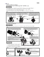
3. While holding Rotor ass’y by a gloved hand,
turn M6 Hex nut counterclockwise with Wrench 10.
Then remove Spiral bevel gear 10.
4. Hook the jaws of 1R045 with Gear housing cover,
then push out Rotor ass’y.
In this step, Ball bearing 629LLB still remains in
Gear housing cover.
Spiral bevel gear 10
Gear housing cover
M6 Hex nut
1R286
Rotor ass’y
Gear housing cover
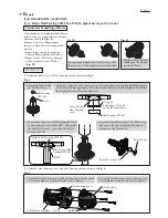
Ball bearing 629LLB
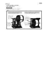
Ball bearing 629LLB
5. Press down Ball bearing 629LLB with 1R286.
Small hole
Gear housing cover
Note
: Face the small hole toward upward.
Do not face the large hole toward
upward. (Refer to
Fig. 4 of Page 4.
)
Ball bearing
607LLB
1R269
6. Remove Ball bearing 607LLB with 1R269.
1R045
Notch of Gear housing cover
Fig. 2
Gear housing
P 3/ 11
4x30 Tapping screw
(4 pcs.)
Rotor ass’y
R
epair