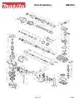
background image

P 3 /14

R

epair

17

Gear housing comp.

Gear room

Inner circumference of Oil seal

Swash bearing 10

Surface that contacts Helical gear 26 and the inside surface that
contacts Cam shaft

Crank room where Piston cylinder thrusts

Item No.

Amount to apply

Description

Portion to lubricate

65

Inner housing comp.

Fig. 2

[2] -2. Makita Grease RB No.00

:Makita grease RB No.00

about 17g

52

Cap 35

Inside surface that contacts hammer bit

Inner circumference that contacts Tool holder comp.

Needle bearing comp.

Inside surface

Inner circumference

27

Spur gear 51

appropriate amount

18

Steel ball 7.0

Whole surface

Face of cam and the surface that contacts Inner housing comp.

29

Tool holder comp.

28

X ring 9

Inner circumference

Surface that contacts Tool holder comp.

32

Sleeve 9

31

Ring 10

Surface that contacts Cushion ring 13

Whole surface

38

O ring 9

35

Whole surface

41

O ring 16

Piston cylinder

Inside surface that contacts Striker

Teeth portion and the inside surface that contacts Cam shaft

49

Spur gear 10

42

Both faces of cam and the inside surface that contacts Cam shaft

50

Clutch cam

Teeth portion

53

Helical gear 26

Whole surface

48

O ring 63

Inner circumference that contacts Armature shaft

67

Oil seal 8

Whole surface

66

O ring 24

Ring 21

appropriate amount

appropriate amount

Ball portion

about 4g

about 5g

appropriate amount

appropriate amount

appropriate amount

4

1

Change lever comp.

Two pins

Whole surface

O ring 17

16

13

52

53

66

Oil seal

1

4

17

13

16

18

28

Cushion ring 13

41

42

50

49

Cam shaft

54

65

67

27

29

31

32

35

38

Содержание BHR240

Страница 1: ...e Net Weight kg lbs Grip Assembly 1 set Depth Gauge Stopper Pole 1 pc SDS Plus bits Taper shank T C T bits Taper shank adapter Cotter Drill chuck assembly Chuck adapter Drill chuck S13 Bull points Dus...

Страница 2: ...rmature holder 32 Fixing Tool holder Removing installing Ring spring 19 for modular use with 1R003 1R212 Tip for retaining ring pliers Installing Oil seal 25 1R232 Pipe 30 Removing Oil seal 25 1R252 R...

Страница 3: ...older comp 28 X ring 9 Inner circumference Surface that contacts Tool holder comp 32 Sleeve 9 31 Ring 10 Surface that contacts Cushion ring 13 Whole surface 38 O ring 9 35 Whole surface 41 O ring 16 P...

Страница 4: ...washer and Conical compression spring 21 29 Fig 5 ASSEMBLING Do the reverse of the disassembling steps Note Conical compression spring 21 29 and Ring spring 19 are not reversible when assembled to To...

Страница 5: ...lace the provisionally assembled Change lever within the area A of Gear housing Fig 8 and insert into the Change lever installation hole Change lever cannot be inserted completely in this step 4 Pushi...

Страница 6: ...ction Figs 3 4 5 in page 4 and Change lever Figs 7 8 2 Separate Gear housing from Motor housing Fig 12 Remove Armature from Gear housing Fig 13 3 Remove the assembly of Tool holder section and Inner h...

Страница 7: ...trated in Fig 17 3 Clamp Tool holder complete using Vise and 1R038 as illustrated in Fig 18 4 Insert a slotted screwdriver between Ring spring 28 and O ring case through the side hole of Tool holder I...

Страница 8: ...g 22 3 6 Swash Bearing Section DISASSEMBLING Impact bolt section X ring 9 O ring 16 Ring 10 O ring 9 Sleeve 9 Impact bolt Cushion ring 13 O ring case Fig 23 Piston cylinder as an assembling jig Note N...

Страница 9: ...he rear dead center position Inner housing Swash bearing section Fig 28 Fig 29 Fig 30 6 Remove Ball bearing 606ZZ from Gear housing complete using the removed Swash bearing section as a jig as follows...

Страница 10: ...ASSEMBLING 1 Assemble Swash bearing section using 1R034 as illustrated in Fig 33 Note 1 Be sure to put Flat washer 8 in place or Bearing retainer will be clamped between Ball bearing 608ZZ and Helica...

Страница 11: ...ig 38 assemble Change plate to Inner housing and Clutch cam to Cam shaft at the same time Put Spur gear 10 and Compression spring 7 through Cam shaft and secure them with Retaining ring S 7 Put Compre...

Страница 12: ...5 Face 34mm side to Oil seal 25 in Gear housing complete 1R164 Gear Housing Complete 1 Pass F R change lever s tab through switch cover left in Fig 42 2 Mount switch cover to switch by fitting the pro...

Страница 13: ...Circuit diagram P 13 14 Yoke Unit Heat Sink F E T Terminal End bell Complete Color index of lead wires sheath Black Red Blue Fig D 1 Yellow Switch Tape to bundle the lead wires...

Страница 14: ...following lead wires with band FET s lead wires black blue yellow Switch s lead wire red Rib A FET Rib C Route he following lead wire between rib B and rib C Switch s lead wires black and red FET s l...

Отзывы: