P 7 / 14
R
epair
[3] DISASSEMBLY/ASSEMBLY
[3] -4. Tool Holder Complete and Spur Gear 51 (cont.)
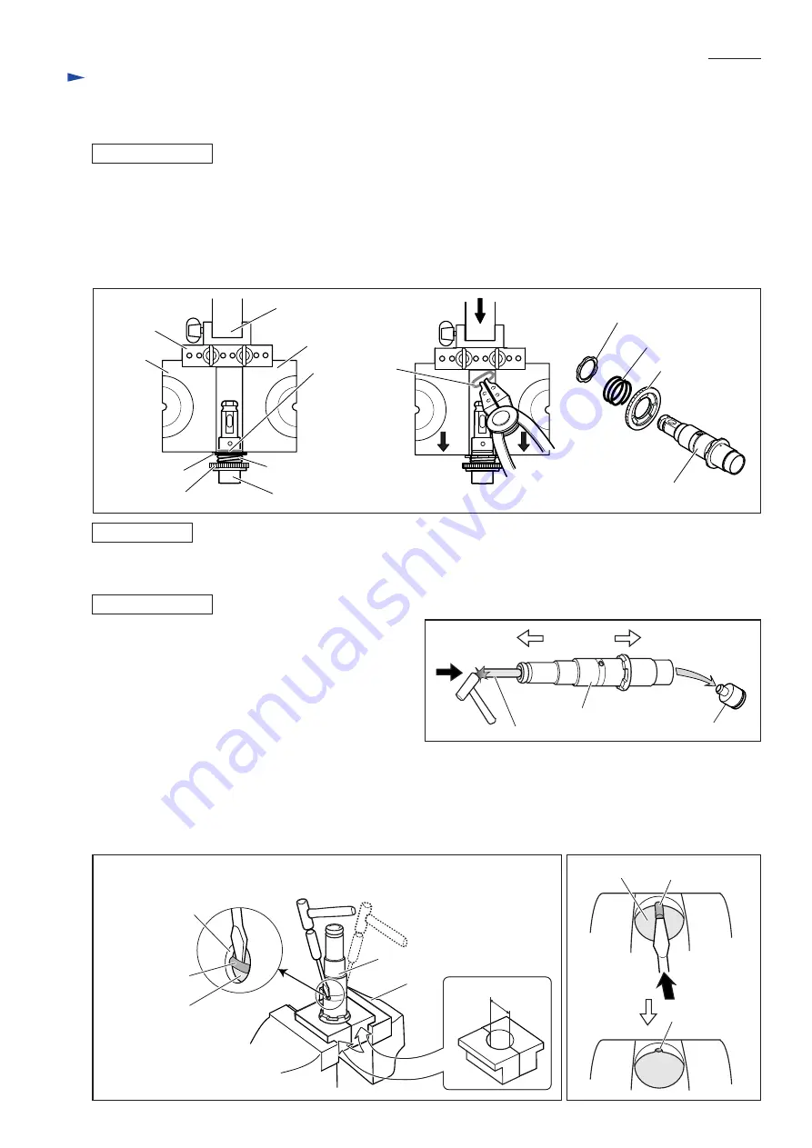
DISASSEMBLING
5) Attach two 1R022 to 1R306.
Install them on arbor press as illustrated to left in Fig. 16.
6) Applying two 1R022 to Washer 31, press them down using arbor press in order to remove the force of
Compression spring 32 from Ring spring 29 (center of Fig. 16).
7) While pressing Washer 31, remove Ring spring 29 from Tool holder complete. (center of Fig. 16)
8) Remove Washer 31, Compression spring 32 and Spur gear 51 from Tool holder complete. (right in Fig. 16)
ASSEMBLING
Do the reverse of the disassembling steps.
Fig. 16
[3] -5. Impact Bolt Section
DISASSEMBLING
1) Take Tool holder complete out of the machine as
illustrated in Fig. 14 and Fig. 15.
2) Remove Striker from Tool holder complete using 1R281
for 1R281 as illustrated in Fig. 17.
3) Clamp Tool holder complete using Vise and 1R038 as
illustrated in Fig. 18.
4) Insert a slotted screwdriver between Ring spring 28 and
O ring case through the side hole of Tool holder.
Important: If you see the end of Ring spring 28 in the hole, push the spring using a slotted screwdriver until the end
is hidden (Fig. 19).
Strike the slotted screwdriver with plastic hammer to remove Ring spring 28 from the groove on the inside surface of
Tool holder complete. Applying slotted screwdriver through the other side hole, remove Ring spring 28 from the groove
in the same way (Fig. 18).
Fig. 17
Tool holder complete
Compression spring 32
Compression spring 32
Spur gear 51
Washer 31
Ring spring 29
1R022
1R022
Arbor press
1R306
Spur gear 51
Washer 31
Tool holder complete
Cap 35 side
Inner housing side
Striker
Tool holder complete
1R281
Ring spring 28
O ring case
Fig. 19
Fig. 18
32mm
1R038
Vise
Ring spring 28
O ring case
Tool holder complete
Side hole of Tool
holder complete
Ring spring 28


