Maker Factory MF-4992453 Скачать руководство пользователя страница 54

54

5V & GND

Stabilised 5 V/DC/1000 mA are available at these pins. This connector is available for proper extensions and experiments ("5V" = 

positive pole, "GND" = negative pole).

3.3V PWR-LED

The red LED indicates that the 3.3 V voltage/power supply is working. It lights up when a power supply is connected to the BAT 

connector.

5V PWR-LED

The red LED indicates that the 5 V voltage/power supply is working. It lights up when a power supply is connected to the BAT 

connector.

J7

The jumper "J7" deactivates the evaluation of the PS2-compatible gamepad in the locomotion controller firmware (the robot can 

then no longer be controlled via the gamepad). The gamepad control commands can then only be read out via the user board!

ISP-M

ISP connector ("in-system programming") of the Locomotion controller. Via this connector the locomotion controller can be pro-

grammed via an ISP programming device. It is also possible to use this connector to integrate your own components with SPI 

interface.

PS2-1 - PS2-3

A PS2-compatible gamepad, available as an accessory, can be connected to these pins. With this controller the robot can be con-

trolled manually, similar to a remote controlled car.

J2 & J3

The two sockets are connected to the I2C-BUS connector of the Locomotion controller and can be used for proper extensions. The 

connectors are compatible with the "SEEED-GROVE" components.

J4 & J5

The two sockets are connected to the I2C-BUS connector of the user board and can be used for proper extensions. The connectors 

are compatible with the "SEEED-GROVE" components.

RESET-M

The button triggers a hardware reset of the Locomotion controller when pressed.

S0 - S17 

The "leg servos" of the Hexapod are connected to these connections. The pin headers are always arranged in blocks, which are 

assigned to the respective leg. The connections for "Coxa - Hip", "Femur - Thigh" and "Tibia - Shin" are counted from the respective 

label (S...). The pins are compatible with the most common servos. Make sure the polarity is correct. The polarity is marked on the 

board with "SIG" for the signal line, "BAT+" for the positive pole and "GND" for the negative pole.

SA0 - SA5

The analogue inputs SA0 to SA5 can be used for proper extensions in the locomotion firmware. In the "Motion Firmware" these can 

also be queried by the user board via a function.

SJ1

The PCB jumper "SJ1" connects the audio amplifier with the locomotion controller. In most practical cases, this connection remains 

in place. If necessary, you can carefully cut the jumper with a small wallpaper knife. With a soldering iron and some solder you can 

re-establish the connection.

Loudspeaker

The loudspeaker is used to output the signal tones and is connected to the audio amplifier. The signal tones can be generated by 

the locomotion controller and also by the user board.

Vol.

The trimmer "Vol." is used to adjust the volume of the signal tones of the locomotion controller and the user board. If you turn the 

trimmer in the direction of the buttons, the volume is increased; in the opposite direction it becomes quieter. In practice, a small 

watchmaker's screwdriver has been used to adjust the small trimmer. Be careful not to damage the trimmer when adjusting it! The 

basic setting is the middle position of the trimmer.

T1 & T2

The buttons "T1" and "T2" can be used with the user board. Please take a look at the software examples.

SJ6 & SJ7

The PCB jumpers "SJ6" and "SJ7" connect the outputs of the buttons "T1" and "T2" with a 22 kOhm pull-up resistor, so that no 

pull-up resistors have to be activated in the user board program. In most practical cases, this connection remains in place. If neces-

sary, you can carefully cut the jumpers with a small wallpaper knife. With a soldering iron and some solder you can re-establish 

the connection.

RESET-U

The "RESET-U" button resets the user board.

SJ2

The PCB jumper "SJ2" connects the button "T2" with the NodeMCU user board. The used pin of the NodeMCU is the analogue 

input and can be disconnected from the push-button "T2" by this jumper if used otherwise. Normally this connection remains in 

place. If necessary, you can cut the jumper carefully with a small wallpaper knife. With a soldering iron and some solder you can 

re-establish the connection.

SU1 - SU3

The connectors SU1, SU2 and SU3 are connected to the user board slots and can be used for proper applications. They have the 

same polarity as the servo connectors of the leg servos. Please take a look at the software examples.

µSD

The card slot for a MicroSD card is connected to the Arduino-UNO compatible user board slot and can be used for own applications. 

Please take a look at the software examples.

ISP-U

ISP port ("In-System Programming") of the Arduino UNO compatible user board slot. This port is used to programme the user board 

using an ISP programmer. It is also possible to use this connector to integrate your own components with SPI interface.

  The Locomotion-Controller is located under the loudspeaker.

Содержание MF-4992453

Страница 1: ...Operating Instructions Hexapod Robobug Complete Set Item no 1664151...

Страница 2: ...ling the mechanical parts 18 a Mounting servos 18 b Mounting of bearings 20 c Mounting the servo disks 22 d Mounting the spacer 24 e Mounting the servos on the top plate 25 f Mount bottom plate 27 g M...

Страница 3: ...3 Page 27 Disposal 64 a Product 64 b Batteries Rechargeable Batteries 64 28 Technical Data 65 a General information 65 b Control electronics 65 c Gamepad 65...

Страница 4: ...age The product is aimed at advanced users who already have experience with Arduino and the programming language C C and also in electronics as well as in the construction of mechanical kits The prod...

Страница 5: ...ur own Hexapod running robot and enter the exciting world of robotics The Hexapod Robobug complete set is the ideal basis for entering the fields of electronics mechanics and programming it enables a...

Страница 6: ...nnections for your own expansions Serial data connection between user board and locomotion controller Compatible with the following additional boards Arduino NodeMCU SBC e g Raspberry Pi USB programmi...

Страница 7: ...direct sunlight strong vibrations high humidity moisture combustible gases vapours and solvents Never expose the product to mechanical stress When connecting the servos other components and their conn...

Страница 8: ...or tilt unit e g Conrad item no 1762877 Arduino UNO e g Conrad item no 191789 Screw locking e g Conrad item no 1613301 The Pan Tilt unit is the head mechanism see Figure 1 and can optionally be printe...

Страница 9: ...g the screws be careful not to tighten them too tightly This can lead to damage to the plastic parts loss of warranty guarantee The screws are already delivered pre sorted in small bags You can alread...

Страница 10: ...not use too much screw lock a small drop is sufficient b Ball bearings and cylindrical pins The leg servos are additionally stabilised by ball bearings with pressed in cylindrical pins This significan...

Страница 11: ...the battery looks clean at the end of the soldering work and indicates that there is no danger of a short circuit In figure 7 you can see how the battery is plugged into the Robobug The plug is prote...

Страница 12: ...driver manually during installation The driver is located in the unpacked download bundle in the Driver directory After installing the driver check in the device manager whether the driver for the Hex...

Страница 13: ...in the menu item File Examples Maker Factory Hexapod Vx x The folder Locomotion contains programmes for the Locomotion controller which is fixed on the Hexapod Robot Board and is responsible for the...

Страница 14: ...rammes to be transferred called sketches in the Arduino IDE that are intended for the locomotion controller For the user board samples you only change the applied user board in use and the COM Port Pl...

Страница 15: ...como tion directory to the Hexapod Robot Board The programme automatically moves the servos from S0 to S17 to the middle position Connect the servos to the pin headers as shown in the figure pay atten...

Страница 16: ...leg Right Rear RM Right Middle leg Right Middle RF Right front leg Right Front LR Left rear leg Left Rear LM Left middle leg Left Middle LF Left front leg Left Front Leave the programme on the Hexapo...

Страница 17: ...graphic illustrates the pulse pause ratio required to control a servo In this case the pulse has a length of 1 5 ms 1500 s which corresponds to the centre position of the servo A servo receives as con...

Страница 18: ...tly rounded side due to the manufacturing process punching process You can use the parts in both directions during as sembly The nicer side should point forward in the direction of travel The rounded...

Страница 19: ...the round opening at the top and the servo cable for the femur servo is inserted through the large oval opening as with the U angle mounting Screw the servos together with four plastic screws When sc...

Страница 20: ...too large the bearing can be glued to the flange of the bearing with a small drop of glue e g Uhu Endfest or comparable The bearings may come loose during final assembly due to uneven pressing of the...

Страница 21: ...of 6 times Figure 27 shows how you can push the bearing into the aluminium part by hand The bearing should snap into the bore provided with a bold push Make sure that the edge of the bearing is flush...

Страница 22: ...r holes remain free These screws all M2 are now already provided with a screw lock Required tool PH1 Phillips screwdriver Small flat nose pliers or wrench for M2 nut SW4 Screw locking medium strength...

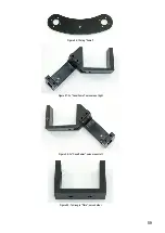
Страница 23: ...23 The femur servo mount must be mounted a total of 6 times Figure 31 Figure 32...

Страница 24: ...ed spacer to each femur counter bearing Insert the threaded side through the counter bearing and fix it with an M3 nut It is sufficient if the spacers are only tightened by hand Do not tighten these s...

Страница 25: ...r the general mechanical tolerances you are not yet able to align the legs too precisely this is not a problem Adjust the leg as mechanically as possible as shown in the illustration An exact calibrat...

Страница 26: ...26 Figure 37...

Страница 27: ...lace an underlay such as a cardboard box between the component and the table so that you do not scratch the table with the screw heads The foam from the packaging for instance is very suitable for thi...

Страница 28: ...ring and the plastic holder and press the cylinder pins into the plastic holder with moderate force If a cylindrical pin has been pressed in too far by mistake you can correct this with a wide slotted...

Страница 29: ...he cable into the receiver as shown in Figure 42 The POWER and RX labels point upwards in the illustration Use the same colour sequence as shown in the illustration Shorten the double sided adhesive t...

Страница 30: ...icroSD card holder position to right battery plug position White grey purple White points to outer edge of board Blue green yellow Blue points to the outer edge of the board Orange red brown Orange po...

Страница 31: ...tightly as this will allow you to readjust them easily to mount the PCB without tension Only when the board has been fixed to the spacers with four screws M3 x 6 mm small head diameter 5 mm tighten t...

Страница 32: ...ure 17 once again shows the pin assignment of the robot board for the leg servos The following list shows wherein each servo is connected Basically the connection sequence COXA FEMUR TIBA always appli...

Страница 33: ...a small drop of screw lock During operation they will loosen quickly and may get lost Required tool PH2 Phillips screwdriver Open end wrench SW 5 5 mm Despite the angled tibia servos femur must be pa...

Страница 34: ...a M3 x 6 mm screw small head diameter 5 mm as shown in Figure 53 The 1 5 mm hexagon key is placed between the ball bearing and the plastic part and the cylindrical pin is pressed in until it stops Als...

Страница 35: ...e been tightened cut off the protruding part of the cable tie A clean cable laying gives the robot a very high quality appearance As long as you have not finished aligning the cables you should not ti...

Страница 36: ...36 Figure 58 Figure 59...

Страница 37: ...37 Figure 60 Illustration_61 Figure 61...

Страница 38: ...38 Figure 62...

Страница 39: ...p on the battery plate and cannot slip during operation Then run the cable through the top plate as shown in Figure 64a Screw the battery retaining plate to the lower plate Use the screws M4 x 5 mm fo...

Страница 40: ...during operation The rubber feet not only secure a good grip on the ground but also ensure that the aluminium legs do not scratch the ground floor table etc l Setting jumpers Finally the two jumpers a...

Страница 41: ...ctly polarity Are all servos mechanically in the middle Is the Gamepad controller connected Is the battery sufficiently charged Is there enough space available for the robot even in the event of a mal...

Страница 42: ...ck values and buttons from the user board and use them in your own program Important Make sure that the receiver is connected correctly and that the plugs are not twisted on the pin strips otherwise t...

Страница 43: ...y rotate mode toggle function 12 On off switch 13 Select gait Tripod 6 Tripod 8 Tripple 12 Tripple 16 Ripple 12 Wave 24 Each time the button is pressed again the gait is shifted through as described i...

Страница 44: ...e and the centre of the M3 cross screws can easily be measured with a ruler The angle can also be easily checked with a ruler by using it as an angle as shown in the illustration The ruler stands with...

Страница 45: ...ext to set the next servo until you have set all 18 servos You can also select a specific leg by clicking on the Leg RR Leg RM Leg RF Leg LR Leg LM and Leg LF buttons Once all servos have been set cli...

Страница 46: ...haracters must be sent to the Hexapod Robot Board until the leg is correctly adjusted Use to select the next servo With a number from 0 to 5 you can select the legs individually 0 Leg RR right rear 1...

Страница 47: ...ader should be regarded universal and represents an interface for proper extensions and developments Arduino UNO Plug an Arduino UNO board onto the robot board as shown in Figure 73 Proceed carefully...

Страница 48: ...tive supply voltage the SBC then supplies the level converters of the robot board with the correct voltage SCL I C clock line connect SCL of the SBC here the I C bus is then available at sockets J2 an...

Страница 49: ...fluctuations and safe operation is not possible via the battery which also supplies the leg servos In this case we recommend to supply the SBC via a small separate power bank In practice a battery cap...

Страница 50: ...nment of your choice The supplied examples are designed for Arduino UNO and NodeMCU boards programmed with the Arduino IDE The Arduino examples show how to use the library These can be found in the Ar...

Страница 51: ...ssigned IP address is displayed in the terminal Type it into your browser Then the browser loads the web interface to control the robot You can then control the robot via WiFi by tapping or clicking t...

Страница 52: ...tput can be realised with the help of the Talkie library Talkie is an implementation of the Texas Instruments ICs speech synthe siser on an Arduino board This IC was very often used in the early 80s T...

Страница 53: ...000 mA at the pins VCC and GND are available This connector is used for proper extensions and experiments VCC positive pole GND negative pole OUT1 This is a digital output of the locomotion controller...

Страница 54: ...omotion controller In most practical cases this connection remains in place If necessary you can carefully cut the jumper with a small wallpaper knife With a soldering iron and some solder you can re...

Страница 55: ...Schematic system overview block diagram The diagram shows schematically the internal wiring and the interaction of the individual components of the robot board and serves as an aid for programming Fig...

Страница 56: ...mounted on this Please also have a look at the additional downloads for the Robobug In the download area there are various 3D printable files available to expand your robot The Pan unit is mounted in...

Страница 57: ...A6 PS2_DAT PA6 28 PS2_CMD PC7 30 PS2_SEL PC5 32 PS2_CLK PC6 31 IR PJ0 15 UB MESS PF3 A3 SOUND PL3 46 Jumper J7 PG5 4 IN1 PA2 24 OUT1 PA1 23 RxD U PD2 RxD1 Serial1 TxD U PD3 TxD1 Serial1 LIVE LED PA0...

Страница 58: ...scope of delivery in larger quantities than necessary These are used as replacements if for example a screw is lost during assembly Figure 82 1x upper plate Figure 83 1x lower plate Figure 84 1x batte...

Страница 59: ...59 Figure 86 12x leg Femur Figure 87 3x Coxa Femur servo mount right Figure 88 3x Coxa Femur servo mount left Figure 89 7x U angle Tibia servo holder...

Страница 60: ...60 Figure 90 18x servo discs Figure 91 18x leg servos Figure 92 1x Robobug board Figure 93 1x PS2 compatible gamepad...

Страница 61: ...ection cable for receiver Figure 96 1x Velcro fastener for fastening the battery pack Figure 97 1x Double sided adhesive tape servo tape for mounting the receiver Figure 98 19x ball bearing with dowel...

Страница 62: ...5 mm for spacers and PCB mounting Figure 103b 18 x Screw M3 x 6 mm PH2 large head diameter 5 mm for spacers and PCB mounting Figure 104 72x Self tapping screw M2 9 x 10 mm for servo mounting Figure 10...

Страница 63: ...onnect the power supply of the robot board switch on the Gamepad and then re establish the connection to the power supply of the Hexapod plug in the battery Is the Gamepad PS2 compatible Jumper J7 mus...

Страница 64: ...d then you will be able to download the EU declaration of conformity in PDF format 27 Disposal a Product Electronic devices are recyclable and do not belong in the household waste Dispose of an unserv...

Страница 65: ...2 I2C connectors User Board 2 IR receiver 1x 38 kHz only usable in combination with Arduino UNO slot or compatible boards Audio amplifier with loudspeaker 1 MicroSD card slot 1 can only be used in co...

Страница 66: ...66...

Страница 67: ...67...

Страница 68: ...ed Reproduction by any method e g photocopy microfilming or the capture in electronic data processing systems require the prior written approval by the editor Reprinting also in part is prohibited Thi...

Отзывы: