background image

BOXER SERIES10-20 KVA 


INSTALLATION 

AG-SD-109 Publishing Date: 13.10.2015 Revision No: 0 Rev. Date:


2. If there is, switch breakers on the battery cabinet to the position of open circuit (OFF). 
 
3. Remove the battery fuse on the battery cabinet. 
 
4. Remove battery fuse on the UPS. 
 
5. Make sure of serial and parallel connections of external battery packs are correct. 
 
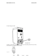
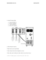
6. Connect the cable to terminals of two of the UPS, "N” (Battery Neutral)”, one "+BAT" and one 
"- BAT" respectively. 
 
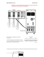
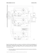
7. Connect four cables that come from UPS to terminals on external battery cabinet or in battery 
room according to external battery connection diagram below. As follows: 


N(UPS)  

-----


Positive Battery Group "-" terminal 


N(UPS)  

-----


Negative Battery Group "+" terminal 


“+ BAT” 

-----


Positive Battery Group “+“ terminal 


“-BAT”    

-----


Negative Battery Group "-" Terminal 

 
8. Make sure that the polarities are connected correctly by checking battery connections for the 
last time. 
 
9. Replace battery fuse on UPS. 
 
10. Replace battery fuse on battery cabinet. 
 
11. If there is, switch breakers on the battery cabinet to the position of closed circuit (ON). 
 
12.  Check if there is appropriate battery voltages to the battery input terminals of the UPS by 
means of a proper measuring device. 


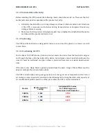
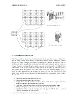
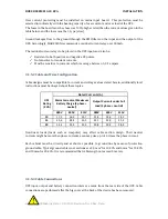
External battery cable selection is determined by application. Fuses which are recommended for 
the UPS and battery cabinet are given. To connect to these type fuses, the lowest diameter cables 
are suggested. Please, refer to the standard called EN 50525-2-31(VDE 0100-430) in this subject. 
The selection should be such that the cable will allow at most 0.5 Vdc decreasing. 
 
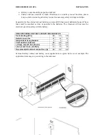
There  exists  "

External  Battery  Temperature  Measurement  Kit

"  to  provide  optimization  of 

the batteries according to battery temperatures in the external battery cabinet application. Thus, 
battery charge temperature can be optimized according to the temperature.  
 
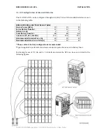
External battery connection scheme is given below: 


Содержание BOXER BX3310

Страница 1: ...USER MANUAL BOXER SERIES 10 20 KVA...

Страница 2: ...USER MANUAL BOXER SERIES 10 20 KVA AG SD 109 Rev 0...

Страница 3: ...Please visit www makelsan com tr for updates Always use the latest manuals Shipment Carrying vehicles or handling accessories must have enough features and characteristics to carry UPS s weight DO NOT...

Страница 4: ...d Mode 10 2 2 3 Bypass Mode 10 2 2 4 Automatic Restart Mode 11 2 2 5 Maintenance Mode 11 2 3 Battery Management 11 2 3 1 Advanced Level Functions Automatic Battery Test 12 2 4 User Panel 13 2 4 1 Open...

Страница 5: ...1 5 5 Control and Communication Cable Connections 34 3 2 Parallel Setup 35 4 OPERATION 39 4 1 Operation Procedure 39 4 1 1 Circuit Breakers 39 4 1 2 First Start Up 39 4 1 3 Testing the Operation Mode...

Страница 6: ...T 5 MINUTES FOR THE DC BUS CAPACITORS TO DISCHARGE AFTER POWER OFF Service Maintenance All service and maintenance operations are performed internally All parts of UPS can be serviced and replaced onl...

Страница 7: ...of UPS through front panel on our products in the range of 10 20 kVA Therefore enough area must be left for operator Furthermore the device can be accessed through the back side for service and mainte...

Страница 8: ...ur wheels By this means it can be easily moved and placed These wheels must only be used on smooth surfaces After the UPS has been placed on an appropriate position front wheels must be locked Back wh...

Страница 9: ...BOXER SERIES 10 20 KVA PRODUCT DESCRIPTION AG SD 109 Publishing Date 13 10 2015 Revision No 0 Rev Date 2 PRODUCT DESCRIPTION General View...

Страница 10: ...0 KVA PRODUCT DESCRIPTION AG SD 109 Publishing Date 13 10 2015 Revision No 0 Rev Date Front View 1 LCD Display 2 Fresh Air Vacuum Grid 3 EPO Emergency Power Off Button 4 Menu Navigation Keys 5 Mimic D...

Страница 11: ...109 Publishing Date 13 10 2015 Revision No 0 Rev Date 1 Rectifier Charger Inverter Cooling Fans 2 Bus Bar Charging Button 3 Optional External Bypass Switch 4 Maintenance Bypass Switch 5 Mains Switch...

Страница 12: ...nal 10 Battery Fast Circuit Breakers and Connecting Terminals 11 Battery Commissioning Switch 12 Output Switch 13 Thyristor Hot Air Evacuation Channel 14 Optional Cold Start Starting through battery S...

Страница 13: ...BOXER SERIES 10 20 KVA PRODUCT DESCRIPTION AG SD 109 Publishing Date 13 10 2015 Revision No 0 Rev Date...

Страница 14: ...or repair are needed before input CB1 and output CB3 circuit breakers are switched to open circuit OFF switch the UPS from normal mode to static bypass mode see 4 1 3 2 Afterwards the maintenance cir...

Страница 15: ...s sensor and the UPS regulates charge parameters in the same way In this case we advise you to order External Battery Temperature Sensor Kit for temperature detection of the UPS 2 2 UPS s Operation Mo...

Страница 16: ...3 Battery Management Constant Charge Current Constant current as 1 10 rate of the battery capacity is applied to battery until the battery reaches the float charge voltage Float Charge Depending on th...

Страница 17: ...od or replace is determined At the end of this test if batteries are reported as replace then the batteries are completely drained after the test In this case loads can remain unpowered in case of mai...

Страница 18: ...inates in battery mode and flashes when UPS is started up through batteries 4 Battery charge indicator LED It illuminates while the batteries are charged 5 Battery module 6 DC AC module Inverter 7 Byp...

Страница 19: ...Restart Auto Battery Test Screen Warning Beep Language Communication Service Menu Version LOGGING Log Code Date Time Log Records Information MAINS Voltage Current Frequency Active Power Reactive Power...

Страница 20: ...urns to the opening screen 2 4 2 Main Menu Switch from opening screen to the main menu through ENT button 2 4 3 Navigating Through the Menus Press UP DOWN keys to move the cursor arrow in the screen O...

Страница 21: ...ts batteries which has more capacity than 10 as Good less capacity than 10 as Replace according to the test results After the device is started and every 24 hours it automatically performs a quick bat...

Страница 22: ...l apparent power and load in percentage of each phase VL CF Voltage of each phase phase neutral and crest factor Bypass VP A Hz Voltage phase neutral current and frequency of each phase VL Voltage of...

Страница 23: ...battery install date via this menu Automatic Restart In battery mode the device operates until batteries discharge and then shuts down Auto restart can be used to restart the UPS automatically when th...

Страница 24: ...etting to make it more visible on different environmental conditions Beeper Turn the beeper sound on off Language Set the menu language Communication Set the protocol for the RS232 connection The opti...

Страница 25: ...tput frequency Hz parallel battery handle number x series battery handle number and battery capacity set on the UPS can be accessed through the version menu 2 4 8 Logging Menu The last 500 logs can be...

Страница 26: ...st be taken in order to protect eyes against electrical arcs that can result from contacts ESD protected rubber gloves should be used Batteries discharging or leaking must not be used if any it must b...

Страница 27: ...ea with cool air flow 3 1 3 1 Positioning the UPS For the Boxer 10 20 KVA Series fresh and cool air enters the device from the front side and goes out through the fans on the back side of the device A...

Страница 28: ...E TABLE Device Power KVA 10 15 20 Series Battery Number 31 31 31 Battery Group 2 2 2 Total Battery Number 62 62 62 I_bat max V_bat_cutoff A 12 5 18 8 25 1 Recommended Internal Fuse A 20 32 40 Recommen...

Страница 29: ...drops the said range the capacity of the battery will seriously decline Therefore expected time will not be obtained during back up As a result keep batteries away from heat sources and serious air fl...

Страница 30: ...nitely be used These fuses must be mounted as close as possible to the batteries This closeness will increase the electrical operation safety with the battery BOXER EXTERNAL BATTERY CABINET CONFIGURAT...

Страница 31: ...specially when batteries are inside of cabinet Move the UPS as rarely as possible 3 1 5 Mains Load and Battery Connections Distribution board is recommended for the UPS outputs Load protection fuses a...

Страница 32: ...esigns must be compatible to current and voltage values stated herein additionally local instructions must be obeyed about these topics UPS Rating KVA Rated Currents A Mains Currents at Maximum Batter...

Страница 33: ...input and output of the UPS Neutral line is not interrupted Please follow the steps below for electrical connections 1 Take all the breakers in the distribution boards open circuit OFF position and ma...

Страница 34: ...AG SD 109 Publishing Date 13 10 2015 Revision No 0 Rev Date 3 Connect the ground cable 4 Make sure that all the circuit breakers are in the open circuit OFF position The use of these circuit breakers...

Страница 35: ...Connect the input cables R phase to INPUT L1 S phase to INPUT L2 T phase to INPUT L3 N Neutral to Input N 6 Check the phase sequence 7 Repeat steps 4 5 for output cables 8 Place the metal cover back...

Страница 36: ...connections in this section 3 1 5 4 1 Internal Battery Installation Procedure and Connection Battery Installation Procedure Follow the procedure below while commissioning internal batteries 1 Remove...

Страница 37: ...nnection You can find details about how to configure the external batteries under External Batteries Configuration title above The information about connection of external batteries and UPS is given i...

Страница 38: ...ctly by checking battery connections for the last time 9 Replace battery fuse on UPS 10 Replace battery fuse on battery cabinet 11 If there is switch breakers on the battery cabinet to the position of...

Страница 39: ...Cable Connections MAKELSAN UPS products have standard or optional connections of advanced external battery cabinet environmental monitoring control panels and various intelligent monitoring Connection...

Страница 40: ...feature is offered as an option Please contact your authorized dealer for parallel operation Parallel application should be made by authorized personnel assigned by MAKELSAN In case of need of redund...

Страница 41: ...d to each other but definitely each battery group is different from another batteries cannot be used in common The following points should be considered while placement of devices in parallel system a...

Страница 42: ...les Each device must have its own neutral cable Each device must have its own ground cable Devices must be connected through the distribution board and phases must be properly connected U1 U2 UN V1 V2...

Страница 43: ...BOXER SERIES10 20 KVA INSTALLATION AG SD 109 Publishing Date 13 10 2015 Revision No 0 Rev Date Software settings on the user panel should be made by authorized personnel...

Страница 44: ...operly Owing to the auxiliary contact detail in CB3 if it is activated while the UPS is operating the mains activates Bypass static switches The system switches to maintenance mode without any interru...

Страница 45: ...position If there exists optional external bypass switch the external bypass breaker CB5 to closed circuit ON position 4 Start the UPS using the front panel Main Menu Control Password Start 5 Check t...

Страница 46: ...dio alerts in an overload condition without feeding critical AC loads 4 1 3 Testing the Operation Modes of the UPS After first start up switch among operation modes with the aim of control 4 1 3 1 Swi...

Страница 47: ...mimic diagram Main Menu Control Switch to UPS Note The inverter will not undertake the load if the inverter voltage is out of limits or there is overload or over temperature situation 4 1 3 4 Switchi...

Страница 48: ...LANATIONS OF LOGGING AG SD 109 Publishing Date 13 10 2015 Revision No 0 Rev Date Main Menu Control Switch to BYPASS 1 Take CB2 to closed circuit ON position 2 Stop the UPS using the front panel Main M...

Страница 49: ...3 and CB4 to open circuit OFF position FOR SAFETY WAIT 5 MINUTES AT LEAST BEFORE OPENING UP THE DEVICE AFTER YOU HAVE SWITCHED THE DEVICE TO THE MAINTENANCE BYPASS MODE 4 1 4 Performing a Complete Shu...

Страница 50: ...FORE PERFORMING A COMPLETE SHUTDOWN 4 1 5 EPO Emergency Power OFF By pressing the EPO button the UPS turns the rectifier and the inverter off respectively If the output breaker turn off option is set...

Страница 51: ...ge value while UPS was operating on the battery mode 10 Overload Timeout UPS has operated at overload more than time limit adjusted The Loads will be transferred to bypass line 11 End of Battery Test...

Страница 52: ...s back to normal 28 Maintenance BYPASS Switch Off Maintenance bypass switch is deactivated 29 Normal Ambient Temp UPS ambient temperature has got back to allowed limit values 30 Normal Mains Voltage M...

Страница 53: ...tor cannot be activated Load will be transferred to inverter line 50 BYPASS ThyristorL2Open Circuit UPS has detected that bypass L2 thyristor cannot be activated Load will be transferred to inverter l...

Страница 54: ...us of static switches 74 No Parallel CAN Bus Communication Slave UPS which is operating in parallel mode can t reach to master UPS from CAN bus If UPS is operating will be shut down 75 Externally Star...

Страница 55: ...otection is activated in rectifier L1 phase 93 PFC FL2 Over Current Short circuit protection is activated in rectifier L2 phase 94 PFC FL3 Over Current Short circuit protection is activated in rectifi...

Страница 56: ...BOXER SERIES 10 20 KVA EXPLANATIONS OF LOGGING AG SD 109 Publishing Date 13 10 2015 Revision No 0 Rev Date...

Страница 57: ...ncy Up to 93 Output Frequency Range In 50Hz 0 5 range synchronous with the network 50Hz 0 2 battery mode Output Harmonic Distortion THDv Linear Load 2 Non Linear Load 6 Crest Factor CF 3 1 Overload Ca...

Страница 58: ...001 LVD Safety IEC 62040 1 IEC 60950 EMC IEC 62040 2 GENERAL Running Temperature 0 C 40 C range for batteries 0 25 C Storage Temperature 15 C 45 C range for batteries 10 60 C Protection Class IP20 Cha...

Страница 59: ...i 2 Yol I 5 Parsel 34956 Tuzla stanbul Tel 0216 428 65 80 Fax 0216 327 51 64 E mail makelsan makelsan com tr zmir Office Halkap nar Mah 1348 Sok 2AE Keremo lu Merkezi Yeni ehir zmir Tel 0232 469 47 00...

Страница 60: ...zla stanbul Tel 0216 428 65 80 Fax 0216 327 51 64 E mail makelsan makelsan com tr zmir Office Halkap nar Mah 1348 Sok 2AE Keremo lu Merkezi Yeni ehir zmir Tel 0232 469 47 00 Fax 0232 449 47 00 E mail...

Отзывы: