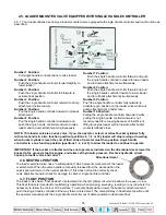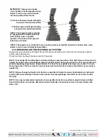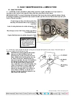
background image


24

3.4. HYDRAULIC INSTALLATION 

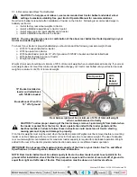
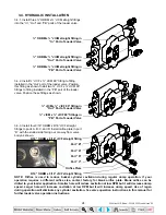
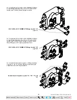
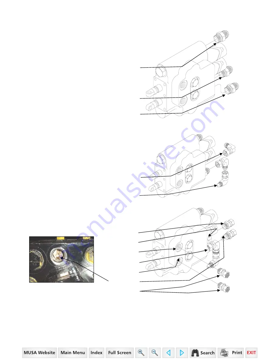
3.4.1. Install three ¾” ORBM x ¾” JICM straight fittings 
into the “In”, “Out” and “PB” ports of the loader valve. 


¾” ORBM x ¾” JICM straight fitting in

“In” Port of Loader Valve


¾” ORBM x ¾” JICM straight fitting in

“Out” Port of Loader Valve

¾” ORBM x ¾” JICM straight fitting in

“PB” Port of Loader Valve


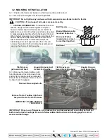
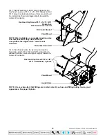
3.4.2. Install ¾” JICF x ¾” JICM 90° fitting to fitting 
installed in the “Out” port of the loader valve. Position 
this fitting as shown. Install two ¾” JICF x ¾” JICM 90° 
fittings to fitting installed in the “PB” port of the loader 
valve. Position these fittings as shown. 


¾” JICM x ¾” JICF 90° fitting in

“Out” Port of Loader Valve

¾” JICM x ¾” JICF 90° fittings in

“PB” Port of Loader Valve


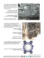
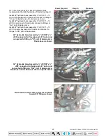
3.4.3. Install four 9/16” ORBM x 9/16” JICF straight 
fittings to ports A, B, C and D. Install orifice plate in port 
“D” with the slotted side facing out or away from valve 
body as shown. 

9/16” ORBM x 9/16” JICF straight fitting


Port “B”  


Port “A”  


  Port “D”


     Port “C”


Orifice Plate


9/16” ORBM x 9/16” JICF straight fitting


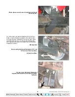
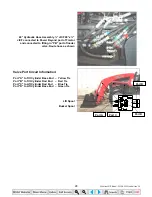
NOTE: Orifice is used to reduce bucket cylinder cavitation during regular dump operation. If your 
operation requires a different orifice size, contact factory for blank orifice plate. Blank orifice can be 
drilled to your loader application. Smaller hole will reduce cavitation at low RPM but it will decrease dump 
speed. Larger hole will increase cavitation at low RPM but it will increase dump speed. Use of regen 
during operation will eliminate any cylinder cavitation. See valve operation instructions in this manual for 
further loader valve operation instructions. 
 

35 Series 4WD, Model - 3535 & 4035 Loader June’08

Содержание ML 120 3535

Страница 1: ...Click here to go on INDEX Main Menu contactus almats com OPERATOR S MANUAL PARTS CATALOGUE INSTALLATION INSTRUCTIONS GEAR 35 Series3535 4035 ML 120...

Страница 2: ...Includes Operator s Manual Parts Catalogue and Installation Instructions Mahindra Ltd Model ML120 Front End Loader 1503 1139 February 2008 35 Series 4WD Model 3535 4035 Loader June 08...

Страница 3: ...roved by Mahindra The Mahindra Loaders shall have been used in accordance with the procedures specified in the Operator s Manual This Warranty does not extend to damage resulting from misapplication a...

Страница 4: ...ially hazardous situation which if not avoided could result in death or serious injury CAUTION Indicates a potentially hazardous situation which if not avoided may result in minor or moderate injury I...

Страница 5: ...ised loader or to reach through the loader boom when the bucket or attachment is raised 15 A frequent cause of personal injury or death is persons falling off and being run over Inadvertent movement o...

Страница 6: ...ss the valve handle handles are manually returned to neutral or until relief pressure is reached at the ends of piston strokes Observe the bucket movement and maintain control with valve handle handle...

Страница 7: ...uipment and overhead power lines HYDRAULIC 67 Do not tamper with the relief valve setting This will void warranty and could cause damage to loader and or tractor 68 Escaping hydraulic fluid under pres...

Страница 8: ...ould be taken to park or store attachments with points or sharp edges in a safe manner 87 Make sure all parked loaders are on a hard level surface Engage all safety devices to prevent loader from fall...

Страница 9: ...Keep machine clear of overhead power lines to avoid death or serious injury 0595 3003 WARNING DECAL To prevent rollback onto operator use special loader attachments for handling large objects such as...

Страница 10: ...or carry anyone on buckets forks probes or any other portion of the loader or loader attachments Do not allow riders on tractor loader or forks Avoid contact with electrical power lines by loader or...

Страница 11: ...ecals clean and free of obstructing material 2 Clean safety decals with soap and water and dry with a soft cloth 3 Replace damaged or missing safety decals with new decals from your Mahindra Dealer 4...

Страница 12: ...d free of obstructing material 6 Clean safety decals with soap and water and dry with a soft cloth 7 Replace damaged or missing safety decals with new decals from your Mahindra Dealer 8 If a component...

Страница 13: ...ON LOADER FACTORY ATTACHMENTS 57 10 3 SKID STEER TOOL CARRIER SYSTEM SERVICE LUBRICATION 58 11 INSTALLATION OPERATION OF SKID STEER TOOL CARRIER SYSTEM 59 11 1 INSTALLATION INSTRUCTIONS 59 11 2 SKID S...

Страница 14: ...ACKETS AND HARDWARE 88 25 HYDRAULIC CYLINDERS AND HOSES 90 26 HYDRAULIC VALVE AND HARDWARE 92 27 LIFT CYLINDER 94 28 TILT CYLINDER 95 29 LOADER VALVE 96 30 SKID STEER TOOL CARRIER ATTACHMENT98 31 SKID...

Страница 15: ...cket 12 off ground Specifications taken with Ag Tires 12 16 5 front and 16 9 x 24 rear with 72 skid steer bucket installed on unit Cycle time 1000 rpm 1500 rpm 2000 rpm Full rpm Raise time 10 1 sec 7...

Страница 16: ...or need new parts contact your local Mahindra dealer Your dealer will need the loader model number and serial number to give you prompt efficient service The serial number plate is located on the LH...

Страница 17: ...placed on the tires with the Front End Loader See your tractor Operator Manual Adjust the front tires to the widest recommended setting on adjustable models for maximum stability Front end weights mu...

Страница 18: ...and rolled back with 1250 in bucket Bucket Loader Pivot Pin 12 off of ground Rear Axle weight must be a minimum of 25 of total unit weight when counterbalanced correctly CAUTION To allow proper steer...

Страница 19: ...h other This will increase the preload further locking the assembly and reducing the chance of bolt loosening Bolt Threads Bracket Material and or hardened flatwasher Disc Lock Washer angled grooves m...

Страница 20: ...center bracket to the tractor clutch housing using four 10 x 1 75 Gr 8 bolts and disc lock washers Then install four 5 8 12 x 2 0 bolts and 5 8 disc lock washers in front four holes of center bracket...

Страница 21: ...3 point link plate bolts and secure with hardened flatwasher 5 8 supplied with loader on slotted hole and link plate hardware removed RH Rear Rail Secure using Hardened Flatwasher 5 8 and 3 Point Link...

Страница 22: ...assembly center bracket and rear rail are installed install cross member to right hand and left hand center brackets as shown using four 5 8 12 x 2 0 Gr 8 bolts 5 8 hardened flatwashers and 5 8 stover...

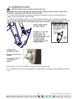
Страница 23: ...e 82 3 2 8 If equipped install tractor tie down hook to each loader centerbracket using hex head cap screw 10 x 2 0 Grade 8 and stover hex locknut 10 2 places as shown Hex Head Cap Screw 10 x 2 0 Grad...

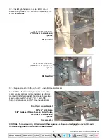
Страница 24: ...ld cause cylinder damage not covered under warranty Secure using pins and hardware 4 places Bucket cylinder grease zerk faces upward Install 1 0 x 4 11 Pivot Pin 3 8 16 x 1 25 Carriage Bolts 3 8 Harde...

Страница 25: ...BM x 9 16 JICF straight fittings to ports A B C and D Install orifice plate in port D with the slotted side facing out or away from valve body as shown 9 16 ORBM x 9 16 JICF straight fitting Port B Po...

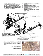
Страница 26: ...BM 45 fittings on two fittings installed in the B and D ports of the loader valve Position these fittings as shown Install these fittings at a 40 angle upward as shown 9 16 JICM x 9 16 ORBM 90 fitting...

Страница 27: ...leted position valve and components so they clear all tractor components then tighten 5 16 valve mount hardware Third hole downward 3 4 8 Install loader valve to valve mount using hex head cap screw 5...

Страница 28: ...raulic hose assembly JICF 90 x JICF to power beyond port of tractor and connect to fittings in PB port of loader valve 22 Hydraulic Hose Assembly JICF 90 x JICF connected to Pressure port of Tractor a...

Страница 29: ...oader valve Route hose as shown Valve Port Circuit Information Port A to Tilt Cylinder Base End Yellow Tie Port B to Tilt Cylinder Rod End Red Tie Port C to Lift Cylinder Rod End Blue Tie Port D to Li...

Страница 30: ...f right hand fender using hex head cap screw 3 8 16 x 1 25 and 3 8 16 stover hex locknut 4 places as shown Single handle controller Mount Hex Head Cap Screw 3 8 16 x 1 25 4 places Tractor Floor Stover...

Страница 31: ...ingle handle controller pivot point located to the lower left corner of single handle controller housing This will ensure proper single handle controller operation Front of Tractor Single handle contr...

Страница 32: ...l the end of the cable is flush with the inside of the spool adapter NOTE Move single handle controller forward and rearward and check to see which cable end moves Install this cable on top or lift sp...

Страница 33: ...ng will distort flange See fig 1 1 12 1 Cable adjuster 1 12 2 Jam nut 1 12 3 Dual Flange 1 12 4 Cable 1 12 5 Jam nut 1 12 6 Spool adapter 1 12 7 Valve spool end 1 12 8 Pin 1 12 9 Metric bolt 3 4 16 Su...

Страница 34: ...ut 5 8 12 as shown Toolbox Hex Head Cap Screw 5 8 12 x 2 5 Stover Hex Locknut 5 8 12 2 places 3 4 18 Install step removed in step 3 2 3 on right hand rear rail using original step hardware as shown Ri...

Страница 35: ...erly installed the loader valve handle will control loader hydraulic circuits as described below IMPORTANT Contaminants in hydraulic fluid can cause valve spools to stick BE ALERT when operating loade...

Страница 36: ...te after bucket contacts rollback stops NOTE This loader valve is a series valve If you the operator extend or retract bucket cylinders fully with valve handle in a two function position positions 6 7...

Страница 37: ...l decal lower the bucket to the ground stop the engine and relieve all hydraulic pressure Recheck hydraulic circuit hookup to loader valve and correct NOTE Use of regen function during dumping will el...

Страница 38: ...Check the tractor hydraulic fluid level and fill if required NOTE Your loader lift and attachment circuits will have some leak down This drift down is normal and is caused by loader valve spool leaka...

Страница 39: ...nting kit hardware from loosening during loader operation hardware must be torqued to specifications noted in operator manual 5 1 2 With the engine off and the bucket on the ground inspect all hoses f...

Страница 40: ...ing hydraulic system fluid level the loader boom must be on the ground with the bucket or attachment resting flat on a level surface 5 2 LOADER LUBRICATION AND SERVICE 5 2 1 There are 12 grease fittin...

Страница 41: ...ent level with ground then relieve all hydraulic pressure CAUTION Do not stand walk or work under a raised loader or attachment unless it is securely blocked or held in position Accidental movement of...

Страница 42: ...e bucket is not completely filled during each pass Maximum productivity is determined by the amount of material loaded in a given period of time Time is lost if two or more attempts are made to fill t...

Страница 43: ...so avoid mixing of surface material with stockpile material The float position will reduce the chance of surface gouging while removing snow or other material or when working with a blade 6 7 LOADING...

Страница 44: ...llow you to concentrate on controlling the bucket angle to maintain a precise cut 6 9 LOADING LOW TRUCKS OR SPREADERS FROM A PILE For faster loading minimize the angle of turn and length of run betwee...

Страница 45: ...ger of rolling the tractor over Danger of upending the tractor Danger of object rolling or sliding down the loader boom onto the operator CAUTION If you must perform the above work protect yourself by...

Страница 46: ...nd void warranty Never use bucket or other attachment in position shown when back grading or dozing material This will cause excessive pressure in bucket cylinder and will cause failure to your loader...

Страница 47: ...es in system causing failure or damage to cylinders hoses or loader frame members Step 1 Extend lift cylinder Step 2 Connect chain or nylon strap to bucket and solid object Step 3 Apply force with buc...

Страница 48: ...Do not allow bystanders in loader work area IMPORTANT Never allow weight of tractor to be placed on parking stand when mounting or dismounting loader 7 1 1 Position the loader on a hard level surface...

Страница 49: ...aring box Handle pin 7 1 5 Remove parking stand from storage position in the boom cross tube Return hairpin cotter to storage position Hairpin cotter in storage position Parking stand in storage posit...

Страница 50: ...bearing boxes Loader is ready to be dismounted Parking stand in park position Handle pins removed from bearing boxes 7 1 8 Retract tilt cylinders A to roll bucket back and retract lift cylinders B to...

Страница 51: ...to guide loader as it is being parked off of tractor Bearing boxes 7 1 11 Retract tilt cylinders G completely 7 1 12 Make sure all loader components clear tractor Back tractor away H slightly 7 1 13 S...

Страница 52: ...n a hard level surface Engage all safety devices to prevent loader from falling and being damaged or injuring someone Do not repair loader if it is not mounted on the tractor Loss of hydraulic fluid o...

Страница 53: ...placed on parking stand when mounting or dismounting loader 8 1 1 To aid in mounting and dismounting loader apply a small amount of grease if needed to each tower in areas of tower bottom receiver A...

Страница 54: ...es Make sure loader is centered right to left on both towers Tower Bearing box top pin Tower top receiver guide post Tower top receiver Bearing box Bearing box centered right to left on tower Bearing...

Страница 55: ...s using snap pins Bearing box Handle pin Snap pin 8 1 9 Remove parking stand from parked position Return clevis pin and hairpin cotter to attaching bracket for storage Clevis pin and hairpin cotter in...

Страница 56: ...position Parking stand in storage position IMPORTANT To avoid hydraulic hose damage be alert and make sure hoses do not catch on tractor and or loader during mounting or dismounting After loader is mo...

Страница 57: ...stall headlight protector assembly to attachment assembly using hardware indicated Headlight Protector Assembly Hex Head Cap Screw 13 x 2 0 Hardened Flatwasher on both sides Stover Hex Locknut 13 2 pl...

Страница 58: ...chment to this Skid Steer Tool Carrier System read and understand the following instructions and safety information Always make sure Skid Steer Tool Carrier is locked onto all attachments NOTE A If yo...

Страница 59: ...ts and pins If damaged only replace with Factory approved components Check and tighten this 1 2 bolt after every 20 hours of operation 1 place each side Lubricate these 2 grease fittings 2 places each...

Страница 60: ...could cause loader damage and void warranty Install Skid Steer Tool Carrier to loader using 1 0 x 4 11 Pivot Pin 3 8 16 x 1 25 Carriage Bolts 3 8 Hardened Flatwashers and 3 8 16 Stover Hex Locknuts 4...

Страница 61: ...pward Rotate handles upward 11 3 SKID STEER TOOL CARRIER HANDLES IN ENGAGED POSITION 11 3 1 To position handles into the handle engaged position rotate skid steer tool carrier handle downward until th...

Страница 62: ...lightly 12 1 2 Position handles into the handle disengaged position rotate skid steer tool carrier handle upward Rotate handles upward 12 1 3 Roll Skid Steer Tool Carrier attachment forward by extendi...

Страница 63: ...rd until they latch into position NOTE Handles should be positioned parallel to ground if properly latched Rotate handles downward 12 1 7 Check that bucket or attachment is securely attached to Skid S...

Страница 64: ...assembly engaging bucket or attachment IMPORTANT If properly latched into skid steer tool carrier attachment the lower groove pin should be contacting pin support bar Lower groove pin Pin support bar...

Страница 65: ...cket or attachment from loader position bucket or attachment slightly rolled back and approximately 1 off of ground 13 1 2 Position handles into the handle disengaged position by rotating skid steer t...

Страница 66: ...ding down the loader arms onto the operator WARNING To avoid serious injury or death Do not lift or carry anyone on buckets forks probes or any other portion of the loader or loader attachments Avoid...

Страница 67: ...00 24 forward of front side of attachment frame CAUTION When transporting a round bale tilt the bale spear slightly back from level and carry the load in a low position CAUTION Never raise round bale...

Страница 68: ...5 ft lb 15 3 INSTALLATION INSTRUCTIONS TO SKID STEER TOOL CARRIER IMPORTANT Refer to Pages 61 to 63 for instructions concerning Installing Attachment to Skid Steer Tool Carrier IMPORTANT Refer to Page...

Страница 69: ...act with electrical power lines by loader or attachments To avoid serious injury or death Do not use pallet fork attachment to lift large objects round bales or items that may roll or slide down loade...

Страница 70: ...Attachment from Skid Steer Tool Carrier 16 4 OPERATING INSTRUCTIONS 16 4 1 The operator must keep the load centered and as far back on the forks as possible Operator must always keep load level Carry...

Страница 71: ...ed Mahindra dealer Category 1 3 point hitch 7 0 cubic feet capacity Category 1 3 point hitch 5 0 cubic feet capacity Refer to section 3 1 4 Recommended Rear Tractor Ballast in front of this manual for...

Страница 72: ...pressure make sure all hydraulic connections are tight and components are in good condition CAUTION Be sure to purge all the air from the hydraulic system before attempting to raise or lower this mac...

Страница 73: ...ower loader and repair or replace damaged lift cylinder If rod end pressure does not increase no cylinder repair is required This test can also be done with some load in bucket and with the loader onl...

Страница 74: ...t from loader valve by disconnecting quick coupler If quick coupler does not exist install one in line before proceeding with this test 18 2 7 Slowly open high pressure ball valve directing drain hose...

Страница 75: ...e distance between the line and the end of the cylinder and subtract the distance from 3 inches to determine how much the cylinder has retracted 18 3 7 Refer to Leak down Rate chart in these instructi...

Страница 76: ...uring cycling Use regen function of valve if your loader is equipped with it when expelling air from the tilt circuit 18 5 3 With the bucket lip approximately level and on the ground place a load in t...

Страница 77: ...0 3 1 2 3 7 8 32 1750 1760 1860 18 7 ACCEPTABLE TILT OR BUCKET CYLINDER LEAK DOWN RATES IMPORTANT Always double check your cylinder size to make sure it matches the information below 18 7 1 Following...

Страница 78: ...ge Check all hoses and tubes for leaks damage or restrictions Replace damaged or restricted hoses or tube lines Cylinder piston assembly defective not sealing Check cylinders for internal leakage as d...

Страница 79: ...linder piston assembly leakage Check cylinders for leakage Repair as needed Loader valve leaking internally Replace loader valve and recheck operation Hydraulic pump defective Refer to Hydraulic Pump...

Страница 80: ...leak and replace defective part Loader valve o rings defective Replace defective o rings Loader valve spool or body damaged or worn Replace loader valve Cylinder rod packing set leakage Check cylinde...

Страница 81: ...perly Inspect clean repair or replace valve Cylinder leaks internally Replace seals Faulty valve Repair or replace valve Loader chatters or vibrates when raising or lowering Air in hydraulic system Cy...

Страница 82: ...controller or cable Replace damaged part and readjust cables Single lever controller hard to operate Cables contaminated Remove cables Replace or clean cables Single Handle Controller will not operate...

Страница 83: ...82 20 TORQUE CHART 35 Series 4WD Model 3535 4035 Loader June 08...

Страница 84: ...umn and are followed by the quantity required and description Directional Reference Right hand RH and left hand LH sides are determined by standing at the rear of the unit and facing in the direction...

Страница 85: ...off if not properly attached To avoid serious injury or death Only use loader manufacturer approved attachments Read all operators manuals and decals before operating Follow all sefaty operating and...

Страница 86: ...cal Mahindra 0595 3101 2 7 Decal Caution 0595 2190 1 8 Decal Warning 0595 3051 1 9 Manual Operator and Parts 1503 1139 1 10 Decal ML120 0595 3127 2 11 Decal Important 0595 3087 2 ML120 9 10 IMPORTANT...

Страница 87: ...86 23 BOOM ASSEMBLY 1 4 2 6 9 3 7 12 13 10 10 7 12 13 8 12 13 8 12 13 5 4 5 11 11 35 Series 4WD Model 3535 4035 Loader June 08...

Страница 88: ...Pin 0551 1234 1 10 Hitch Pin Clip 0553 1000 2 11 Carriage Bolt 3 8 16 x 1 25 0546 1137 8 12 Hardened Flatwasher 3 8 0540 2021 8 13 Stover Hex Locknut 3 8 16 0546 1119 8 14 Decal Warning 0595 3000 1 15...

Страница 89: ...88 24 MOUNTING BRACKETS AND HARDWARE 2 6 17 18 12 14 9 10 15 16 17 13 14 1 3 4 5 7 8 11 15 20 20 19 15 17 17 Tractor Hardware Tractor Hardware 35 Series 4WD Model 3535 4035 Loader June 08...

Страница 90: ...75 Grade 8 0548 2229 8 10 Disc Lock Washer 0540 2017 16 11 Stover Hex Locknut 10 0546 1130 4 12 Hex Head Cap Screw 14 1 50 x 65mm Grade 10 9 0569 2401 8 13 Hex Head Cap Screw 14 2 0 x 35mm Grade 10 9...

Страница 91: ...90 25 HYDRAULIC CYLINDERS AND HOSES 1 11 2 3 4 6 7 8 9 10 12 13 14 14 15 19 17 18 20 21 23 5 35 Series 4WD Model 3535 4035 Loader June 08...

Страница 92: ...ic Hose Assembly 3 8 x 45 RHLCRE 0582 2508848045 1 13 Hydraulic Hose Assembly 3 8 x 17 RHTCBE 0582 2508848017 1 14 Hydraulic Hose Assembly 3 8 x 22 RHTCRE 0582 2508848022 1 15 Hydraulic Hose Assembly...

Страница 93: ...92 26 HYDRAULIC VALVE AND HARDWARE 1 2 3 5 8 4 6 7 18 21 15 18 25 16 17 13 14 10 9 23 22 12 11 27 20 19 18 21 24 29 32 31 30 35 Series 4WD Model 3535 4035 Loader June 08...

Страница 94: ...unt 1204 3147 1 13 Dual Flange 1408 3010 1 14 Cable Adapter Kit 1408 3032 1 15 Valve Mount 1204 3146 1 16 Hex Head Cap Screw 5 16 18 x 625 0545 2023 3 17 Lockwasher 5 16 0544 2009 3 18 Flatwasher 5 16...

Страница 95: ...Cylinder complete 3160 2076 1 1 Tube Assembly 0100 2126 1 2 Nut 0530 2020 1 3 Piston 0405 2041 1 4 Seal Kit 0590 2082 1 5 Head 0330 2046 1 6 Rod Assembly 0200 2116 1 Grease Fitting Straight 0530 1038...

Страница 96: ...ylinder complete 3150 2106 1 1 Tube Assembly 0100 2127 1 2 Nut 0530 2020 1 3 Piston 0405 2041 1 4 Seal Kit 0590 2082 1 5 Head 0330 2045 1 6 Rod Assembly 0200 2117 1 Grease Fitting Straight 0530 1038 2...

Страница 97: ...Float Kit Complete contains all of the following 0580 6351 1 6 Spacer NSS 1 7 Stop Cup NSS 1 8 Spring NSS 1 9 Washer NSS 1 10 Detent Retainer NSS 1 11 Steel Ball NSS 2 12 Spring NSS 1 13 Poppet NSS 1...

Страница 98: ...el Ball NSS 2 12 Spring NSS 1 13 Poppet NSS 1 14 Cap Screw NSS 2 15 End Cap NSS 1 25 Regen Sleeve NSS 1 18 Retainer NSS 1 Valve Body 19 Spool Regen NSS 1 20 Spool Float NSS 1 21 L C Plug Assembly 0580...

Страница 99: ...n that coupler pins are fully engaged Loader attachment can fall off if not properly attached To avoid serious injury or death Only use loader manufacturer approved attachments Read all operators manu...

Страница 100: ...in 1304 3041 2 10 Hex Lock Nut Dimpled 1 2 13NC 0555 2136 4 11 Stop Assembly 1304 3045 2 12 Compression Spring 0565 2004 2 13 Rod Assembly 1304 3068 2 14 Locking Pin 1304 3066 2 15 Socket Head Shoulde...

Страница 101: ...100 31 SKID STEER BUCKET Reference Description Part No Qty 1 Skid Steer Bucket 72 1300 3605 1 1 35 Series 4WD Model 3535 4035 Loader June 08...

Страница 102: ...ales or items that may roll or slide down loader arms onto the operator Always keep pallet forks level when raising loads Avoid raising loads to full heights with pallet forks rolled back Always trans...

Страница 103: ...Bale Spear 1305 2023 1 1 Bale Spear Frame 1305 2024 1 2 Tine Assembly w nut 1250 mm 1305 2013 1 3 Tine Assembly w nut 900 mm 1305 2012 1 4 Decal Caution 0595 2190 1 5 Decal Danger 0595 3050 1 6 Decal...

Страница 104: ...ad Cap Screw 5 8 12 x 2 0 Gr 8 0548 2166 4 4 Hardened Flatwasher 5 8 0540 2004 4 5 Stover Hex Locknut 5 8 12 0546 1134 4 6 Hex Head Cap Screw 13 x 2 0 Gr 5 0545 2108 2 7 Hardened Flatwasher 0540 2003...

Отзывы:

Похожие инструкции для ML 120 3535