18
3.2. MOUNTING KIT INSTALLATION
3.2.1. Position the tractor and loader on a hard level surface under a hoist.
3.2.2. Remove front weights from tractor if applicable.
IMPORTANT: Do not tighten any hardware until all components are attached onto the tractor.
CAUTION: Lift and support all loader components safely.
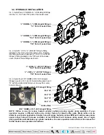
1.
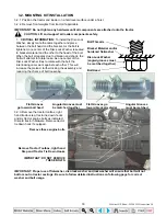
CRITICAL INFORMATION:
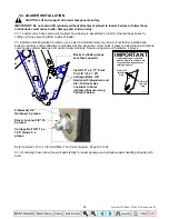
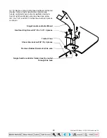
To install the Disc-Lock
Washer, simply mate the cams together and place
between the bolt head and the bracket. As the bolt is
tightened, one center of the Disc-Lock Washer is seated
to bracket material and the other to the head of the bolt.
When the bolt elongates due to vibration and shock, the
bolt will attempt to rotate loose. As one center of the
Disc-Lock Washer tries to rotate with the bolt, the
interlocking cams work against each other. This will
increase the preload, further locking the assembly and
reducing the chance of bolt loosening.
Bolt Threads
Bracket Material and/or
hardened flatwasher
Disc-Lock Washer
(angled grooves must
be matched together)
Bolt Head
Flat Grooves
Angular Grooves must
go toward bolt head
be matched together
Flat Grooves go
Angular Grooves
toward bracket material
must be matched
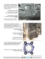
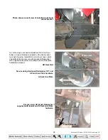
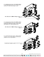
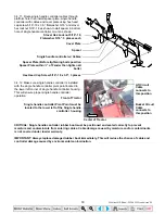
3.2.3. Remove the tractor toolbox, right
hand tractor step, tractor tie down hooks
and six tractor engine bolts as indicated.
Discard tractor hardware. Remove tractor
tie down hook if equipped.
Remove these engine bolts
Remove Tractor Toolbox, right hand
Step and Tractor Tie Down Hooks
IMPORTANT: DO NOT REMOVE
THESE BOLTS
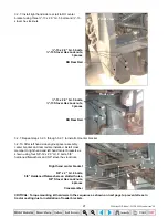
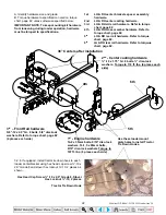
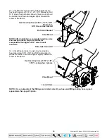
IMPORTANT: Proper use of flatwasher, disc-lock washer and lockwasher will ensure that bolt will not
bottom out in tractor castings. Be sure to follow detailed instructions on following page for correct
washer and bolt usage.
35 Series 4WD, Model - 3535 & 4035 Loader June’08


